
Fun with -fsanitize=undefined and Picolibc
Both GCC and Clang support the -fsanitize=undefined flag which instruments the generated code to detect places where the program wanders into parts of the C language specification which are either undefined or implementation defined. Many of these are also common programming errors. It would be great if there were sanitizers for other easily detected bugs, but for now, at least the undefined sanitizer does catch several useful problems.
Supporting the sanitizer
The sanitizer can be built to either trap on any error or call handlers. In both modes, the same problems are identified, but when trap mode is enabled, the compiler inserts a trap instruction and doesn't expect the program to continue running. When handlers are in use, each identified issue is tagged with a bunch of useful data and then a specific sanitizer handling function is called.
The specific functions are not all that well documented, nor are the parameters they receive. Maybe this is because both compilers provide an implementation of all of the functions they use and don't really expect external implementations to exist? However, to make these useful in an embedded environment, picolibc needs to provide a complete set of handlers that support all versions both gcc and clang as the compiler-provided versions depend upon specific C (and C++) libraries.
Of course, programs can be built in trap-on-error mode, but that makes it much more difficult to figure out what went wrong.
Fixing Sanitizer Issues
Once the sanitizer handlers were implemented, picolibc could be built with them enabled and all of the picolibc tests run to uncover issues within the library.
As with the static analyzer adventure from last year, the vast bulk of sanitizer complaints came from invoking undefined or implementation-defined behavior in harmless ways:
Computing pointers past &array[size+1]. I found no cases where the resulting pointers were actually used, but the mere computation is still undefined behavior. These were fixed by adjusting the code to avoid computing pointers like this. The result was clearer code, which is good.
Signed arithmetic overflow in PRNG code. There are several linear congruential PRNGs in the library which used signed integer arithmetic. The rand48 generator carefully used unsigned short values. Of course, in C, the arithmetic performed on them is done with signed ints if int is wider than short. C specifies signed overflow as undefined, but both gcc and clang generate the expected code anyways. The fixes here were simple; just switch the computations to unsigned arithmetic, adjusting types and inserting casts as required.
Passing pointers to the middle of a data structure. For example, free takes a pointer to the start of an allocation. The management structure appears just before that in memory; computing the address of which appears to be undefined behavior to the compiler. The only fix I could do here was to disable the sanitizer in functions doing these computations -- the sanitizer was mis-detecting correct code and it doesn't provide a way to skip checks on a per-operator basis.
Null pointer plus or minus zero. C says that any arithmetic with the NULL pointer is undefined, even when the value being added or subtracted is zero. The fix here was to create a macro, enabled only when the sanitizer is enabled, which checks for this case and skips the arithmetic.
Discarded computations which overflow. A couple of places computed a value, then checked if that would have overflowed and discard the result. Even though the program doesn't depend upon the computation, its mere presence is undefined behavior. These were fixed by moving the computation into an
elseclause in the overflow check. This inserts an extra branch instruction, which is annoying.Signed integer overflow in math code. There's a common pattern in various functions that want to compare against 1.0. Instead of using the floating point equality operator, they do the computation using the two 32-bit halves with ((hi - 0x3ff00000) | lo) == 0. It's efficient, but because most of these functions store the 'hi' piece in a signed integer (to make checking the sign bit fast), the result is undefined when hi is a large negative value. These were fixed by inserting casts to unsigned types as the results were always tested for equality.
Signed integer shifts
This is one area where the C language spec is just wrong.
For left shift, before C99, it worked on signed integers as a bit-wise
operator, equivalent to the operator on unsigned integers. After that,
left shift of negative integers became undefined. Fortunately, it's
straightforward (if tedious) to work around this issue by just casting
the operand to unsigned, performing the shift and casting it back to
the original type. Picolibc now has an internal macro, lsl, which
does this:
    #define lsl(__x,__s) ((sizeof(__x) == sizeof(char)) ?                   \
                          (__typeof(__x)) ((unsigned char) (__x) << (__s)) :  \
                          (sizeof(__x) == sizeof(short)) ?                  \
                          (__typeof(__x)) ((unsigned short) (__x) << (__s)) : \
                          (sizeof(__x) == sizeof(int)) ?                    \
                          (__typeof(__x)) ((unsigned int) (__x) << (__s)) :   \
                          (sizeof(__x) == sizeof(long)) ?                   \
                          (__typeof(__x)) ((unsigned long) (__x) << (__s)) :  \
                          (sizeof(__x) == sizeof(long long)) ?              \
                          (__typeof(__x)) ((unsigned long long) (__x) << (__s)) : \
                          __undefined_shift_size(__x, __s))
Right shift is significantly more complicated to implement. What we
want is an arithmetic shift with the sign bit being replicated as the
value is shifted rightwards. C defines no such operator. Instead,
right shift of negative integers is implementation
defined. Fortunately, both gcc and clang define the >> operator on
signed integers as arithmetic shift. Also fortunately, C hasn't made
this undefined, so the program itself doesn't end up undefined.
The trouble with arithmetic right shift is that it is not equivalent to right shift of unsigned values. Here's what Per Vognsen came up with using standard C operators:
    int
    __asr_int(int x, int s) {
        return x < 0 ? ~(~x >> s) : x >> s;
    }
When the value is negative, we invert all of the bits (making it positive), shift right, then flip all of the bits back. Both GCC and Clang seem to compile this to a single asr instruction. This function is replicated for each of the five standard integer types and then the set of them wrapped in another sizeof-selecting macro:
    #define asr(__x,__s) ((sizeof(__x) == sizeof(char)) ?           \
                          (__typeof(__x))__asr_char(__x, __s) :       \
                          (sizeof(__x) == sizeof(short)) ?          \
                          (__typeof(__x))__asr_short(__x, __s) :      \
                          (sizeof(__x) == sizeof(int)) ?            \
                          (__typeof(__x))__asr_int(__x, __s) :        \
                          (sizeof(__x) == sizeof(long)) ?           \
                          (__typeof(__x))__asr_long(__x, __s) :       \
                          (sizeof(__x) == sizeof(long long)) ?      \
                          (__typeof(__x))__asr_long_long(__x, __s):   \
                          __undefined_shift_size(__x, __s))
The lsl and asr macros use sizeof instead of the type-generic mechanism to remain compatible with compilers that lack type-generic support.
Once these macros were written, they needed to be applied where required. To preserve the benefits of detecting programming errors, they were only applied where required, not blindly across the whole codebase.
There are a couple of common patterns in the math code using shift operators. One is when computing the exponent value for subnormal numbers.
for (ix = -1022, i = hx << 11; i > 0; i <<= 1)
    ix -= 1;
This code computes the exponent by shifting the significand left by 11 bits (the width of the exponent field) and then incrementally shifting it one bit at a time until the sign flips, which indicates that the most-significant bit is set. Use of the pre-C99 definition of the left shift operator is intentional here; so both shifts are replaced with our lsl operator.
In the implementation of pow, the final exponent is computed as the sum of the two exponents, both of which are in the allowed range. The resulting sum is then tested to see if it is zero or negative to see if the final value is sub-normal:
hx += n << 20;
if (hx >> 20 <= 0)
    /* do sub-normal things */
In this case, the exponent adjustment, n, is a signed value and so
that shift is replaced with the lsl macro. The test value needs to
compute the correct the sign bit, so we replace this with the asr
macro.
Because the right shift operation is not undefined, we only use our fancy macro above when the undefined behavior sanitizer is enabled. On the other hand, the lsl macro should have zero cost and covers undefined behavior, so it is always used.
Actual Bugs Found!
The goal of this little adventure was both to make using the undefined behavior sanitizer with picolibc possible as well as to use the sanitizer to identify bugs in the library code. I fully expected that most of the effort would be spent masking harmless undefined behavior instances, but was hopeful that the effort would also uncover real bugs in the code. I was not disappointed. Through this work, I found (and fixed) eight bugs in the code:
setlocale/newlocale didn't check for NULL locale names
qsort was using uintptr_t to swap data around. On MSP430 in 'large' mode, that's a 20-bit type inside a 32-bit representation.
random() was returning values in
intrange rather thanlong.m68k assembly for memcpy was broken for sizes > 64kB.
freopen returned NULL, even on success
The optimized version of memrchr was always performing unaligned accesses.
String to float conversion had a table missing four values. This caused an array access overflow which resulted in imprecise values in some cases.
vfwscanf mis-parsed floating point values by assuming that
wchar_twas unsigned.
Sanitizer Wishes
While it's great to have a way to detect places in your C code which evoke undefined and implementation defined behaviors, it seems like this tooling could easily be extended to detect other common programming mistakes, even where the code is well defined according to the language spec. An obvious example is in unsigned arithmetic. How many bugs come from this seemingly innocuous line of code?
p = malloc(sizeof(*p) * c);
Because sizeof returns an unsigned value, the resulting computation never results in undefined behavior, even when the multiplication wraps around, so even with the undefined behavior sanitizer enabled, this bug will not be caught. Clang seems to have an unsigned integer overflow sanitizer which should do this, but I couldn't find anything like this in gcc.
Summary
The undefined behavior sanitizers present in clang and gcc both provide useful diagnostics which uncover some common programming errors. In most cases, replacing undefined behavior with defined behavior is straightforward, although the lack of an arithmetic right shift operator in standard C is irksome. I recommend anyone using C to give it a try.
Internationalization support in Picolibc
There are two major internationalization APIs in the C library: locales and iconv. Iconv is an isolated component which only performs charset conversion in ways that don't interact with anything else in the library. Locales affect pretty much every API that deals with strings and covers charset conversion along with a huge range of localized information from character classification to formatting of time, money, people's names, addresses and even standard paper sizes.
Picolibc inherits it's implementation of both of these from newlib. Given that embedded applications rarely need advanced functionality from either these APIs, I hadn't spent much time exploring this space.
Newlib locale code
When run on Cygwin, Newlib's locale support is quite complete as it leverages the underlying Windows locale support. Without Windows support, everything aside from charset conversion and character classification data is stubbed out at the bottom of the stack. Because the implementation can support full locale functionality, the implementation is designed for that, with large data structures and lots of code.
Charset conversion and character classification data for locales is all built-in; none of that can be loaded at runtime. There is support for all of the ISO-8859 charsets, three JIS variants, a bunch of Windows code pages and a few other single-byte encodings.
One oddity in this code is that when using a JIS locale, wide characters are stored in EUC-JP rather than Unicode. Every other locale uses Unicode. This means APIs like wctype are implemented by mapping the JIS-encoded character to Unicode and then using the underlying Unicode character classification tables. One consequence of this is that there isn't any Unicode to JIS mapping provided as it isn't necessary.
When testing the charset conversion and Unicode character classification data, I found numerous minor errors and a couple of pretty significant ones. The JIS conversion code had the most serious issue I found; most of the conversions are in a 2d array which is manually indexed with the wrong value for the length of each row. This led to nearly every translated value being incorrect.
The charset conversion tables and Unicode classification data are now generated using python charset support and the standard Unicode data files. In addition, tests have been added which compare Picolibc to the system C library for every supported charset.
Newlib iconv code
The iconv charset support is completely separate from the locale charset support with a much wider range of supported targets. It also supports loading charset data from files at runtime, which reduces the size of application images.
Because the iconv and locale implementations are completely separate, the charset support isn't the same. Iconv supports a lot more charsets, but it doesn't support all of those available to locales. For example, Iconv has Big5 support which locale lacks. Conversely, locale has Shift-JIS support which iconv does not.
There's also a difference in how charset names are mapped in the two APIs. The locale code has a small fixed set of aliases, which doesn't include things like US-ASCII or ANSI X3.4. In contrast, the iconv code has an extensive database of charset aliases which are compiled into the library.
Picolibc has a few tests for the iconv API which verify charset names and perform some translations. Without an external reference, it's hard to know if the results are correct.
POSIX vs C internationalization
In addition to including the iconv API, POSIX extends locale support in a couple of ways:
Exposing locale objects via the newlocale, uselocale, duplocale and freelocale APIs.
uselocale sets a per-thread locale, rather than the process-wide locale.
Goals for Picolibc internationalization support
For charsets, supporting UTF-8 should cover the bulk of embedded application needs, and even that is probably more than what most applications require. Most (all?) compilers use Unicode for wide character and string constants. That means wchar_t needs to be Unicode in every locale.
Aside from charset support, the rest of the locale infrastructure is heavily focused on creating human-consumable strings. I don't think it's a stretch to say that none of this is very useful these days, even for systems with sophisticated user interactions. For picolibc, the cost to provide any of this would be high.
Having two completely separate charset conversion datasets makes for a confusing and error-prone experience for developers. Replacing iconv with code that leverages the existing locale support for translating between multi-byte and wide-character representations will save a bunch of source code and improve consistency.
Embedded systems can be very sensitive to memory usage, both read-only and read-write. Applications not using internationalization capabilities shouldn't pay a heavy premium even when the library binary is built with support. For the most sensitive targets, the library should be configurable to remove unnecessary functionality.
Picolibc needs to be conforming with at least the C language standard, and as much of POSIX as makes sense. Fortunately, the requirements for C are modest as it only includes a few locale-related APIs and doesn't include iconv.
Finally, picolibc should test these APIs to make sure they conform with relevant standards, especially character set translation and character classification. The easiest way to do this is to reference another implementation of the same API and compare results.
Switching to Unicode for JIS wchar_t
This involved ripping the JIS to Unicode translations out of all of the wide character APIs and inserting them into the translations between multi-byte and wide-char representations. The missing Unicode to JIS translation was kludged by iterating over all JIS code points until a matching Unicode value was found. That's an obvious place for a performance improvement, but at least it works.
Tiny locale
This is a minimal implementation of locales which conforms with the C language standard while providing only charset translation and character classification data. It handles all of the existing charsets, but splits things into three levels
- ASCII
- UTF-8
- Extended, including any or all of: a. ISO 8859 b. Windows code pages and other 8-bit encodings c. JIS (JIS, EUC-JP and Shift-JIS)
When built for ASCII-only, all of the locale support is
short-circuited, except for error checking. In addition, support in
printf and scanf for wide characters is removed by default (it can be
re-enabled with the -Dio-wchar=true meson option). This offers the
smallest code size. Because the wctype APIs (e.g. iswupper) are all locale-specific,
this mode restricts them to ASCII-only, which means they become
wrappers on top of the ctype APIs with added range checking.
When built for UTF-8, character classification for wide characters uses tables that provide the full Unicode range. Setlocale now selects between two locales, "C" and "C.UTF-8". Any locale name other than "C" selects the UTF-8 version. If the locale name contains "." or "-", then the rest of the locale name is taken to be a charset name and matched against the list of supported charsets. In this mode, only "us_ascii", "ascii" and "utf-8" are recognized.
Because a single byte of a utf-8 string with the high-bit set is not a complete character, all of the ctype APIs in this mode can use the same implementation as the ASCII-only mode. This means the small ctype implementation is available.
Calling setlocale(LC_ALL, "C.UTF-8") will allow the application to use the APIs which translate between multi-byte and wide-characters to deal with UTF-8 encoded strings. In addition, scanf and printf can read and write UTF-8 strings into wchar_t strings.
Locale names are converted into locale IDs, an enumeration which lists the available locales. Each ID implies a specific charset as that's the only thing which differs between them. This means a locale can be encoded in a few bytes rather than an array of strings.
In terms of memory usage, applications not using locales and not using the wctype APIs should see only a small increase in code space. That's due to the wchar_t support added to printf and scanf which need to translate between multi-byte and wide-character representations. There aren't any tables required as ASCII and UTF-8 are directly convertible to Unicode. On ARM-v7m, The added code in printf and scanf add up to about 1kB and another 32 bytes of RAM is used.
The big difference when enabling extended charset support is that all of the charset conversion and character classification operations become table driven and dependent on the locale. Depending on the extended charsets supported, these can be quite large. With all of the extended charsets included, this adds an additional 30kB of code and static data and uses another 56 bytes of RAM.
There are two known gaps in functionality compared with the newlib code:
Locale strings that encode different locales for different categories. That's nominally required by POSIX as LC_ALL is supposed to return a string sufficient to restore the locale, but the only category which actually matters is LC_CTYPE.
No nl_langinfo support. This would be fairly easy to add, returning appropriate constant values for each parameter.
Tiny locale was merged to picolibc main in this PR
Tiny iconv
Replacing the bulky newlib iconv code was far easier than swapping locale implementations. Essentially all that iconv does is compute two functions, one which maps from multi-byte to wide-char in one locale and another which maps from wide-char to multi-byte in another locale.
Once the JIS locales were fixed to use Unicode, the new iconv implementation was straightforward. POSIX doesn't provide any _l version of mbrtowc or wcrtomb, so using standard C APIs would have been clunky. Instead, the implementation uses the internal APIs to compute the correct charset conversion functions. The entire implementation fits in under 200 lines of code.
Tiny iconv is in process in this PR
Future directions
Right now, both of these new bits of code sit in the source tree parallel to the old versions. I'm not seeing any particular reason to keep the old versions around; they have provided a useful point of comparison in developing the new code, but I don't think they offer any compelling benefits going forward.
Testing Picolibc with the glibc tests
Picolibc has a bunch of built-in tests, but more testing is always better, right? I decided to see how hard it would be to run some of the tests provided in the GNU C Library (glibc).
Parallel meson build files
Similar to how Picolibc uses meson build files to avoid modifying the newlib autotools infrastructure, I decided to take the glibc code and write meson build rules that would compile the tests against Picolibc header files and link against Picolibc libraries.
I decided to select a single target for this project so I could focus on getting things building and not worry too much about making it portable. I wanted to pick something that had hardware floating point so that I would have rounding modes and exception support, so I picked the ARM Cortex M7 with hard float ABI:
$ arm-none-eabi-gcc -mcpu=cortex-m7 -mfloat-abi=hard
It should be fairly easy to extend this to other targets, but for now,
that's what I've got working. There's a cross-cortex-m7.txt file
containing all of the cross compilation details which is used when
running meson setup.
All of the Picolibc-specific files live in a new picolibc directory so they are isolated from the main glibc code.
Pre-loading a pile of hacks
Adapt Picolibc to support the Glibc test code required a bunch of
random hacks, from providing _unlocked versions of the stdio macros
to stubbing out various unsupportable syscalls (like sleep and
chdir). Instead of modifying the Glibc code, I created a file called
hacks.h which is full of this stuff and used the gcc -include
parameter to read that into the compiler before starting compilation
on all of the files.
Supporting command line parameters
The glibc tests all support a range of command line parameters, some of which turned out to be quite useful for this work. Picolibc had limited semihosting support for accessing the command line, but that required modifying applications to go fetch the command line using a special semihosting function.
To make this easier, I added a new crt0 variant for picolibc called (oddly) semihost. This extends the existing hosted variant by adding a call to the semihosting library to fetch the current command line and splitting that into words at each space. It doesn't handle any quoting, but it's sufficient for the needs here.
Avoiding glibc headers
The glibc tests use some glibc-specific extensions to the standard
POSIX C library, so I needed to include those in the test
builds. Headers for those extensions are mixed in with the rest of the
POSIX standard headers, which conflict with the Picolibc versions. To
work around this, I stuck stub #include files in the picolibc directory
which directly include the appropriate headers for the glibc API
extensions. This includes things like argp.h and
array_length.h. For other headers which weren't actually needed for
picolibc, I created empty files.
Adding more POSIX to Picolibc
At this point, code was compiling but failing to find various standard
POSIX functions which aren't available in Picolibc. That included some
syscalls which could be emulated using semihosting, like
gettimeofday and getpagesize. It also included some generally
useful additions, like replacing ecvtbuf and fcvtbuf with ecvt_r
and fcvt_r. The _r variants provide a target buffer size instead
of assuming that it was large enough as the Picolibc buf variants
did.
Which tests are working?
So far, I've got some of the tests in malloc, math, misc and stdio-common running.
There are a lot of tests in the malloc directory which cover glibc API extensions or require POSIX syscalls not supported by semihosting. I think I've added all of the tests which should be supported.
For the math tests, I'm testing the standard POSIX math APIs in both float and double forms, except for the Bessel and Gamma functions. Picolibc's versions of those are so bad that they violate some pretty basic assumptions about error bounds built into the glibc test code. Until Picolibc gets better versions of these functions, we'll have to skip testing them this way.
In the misc directory, I've only added tests for ecvt, fcvt, gcvt, dirname and hsearch. I don't think there are any other tests there which should work.
Finally, for stdio-common, almost all of the tests expect a fully functioning file system, which semihosting really can't support. As a result, we're only able to run the printf, scanf and some of the sprintf tests.
All in all, we're running 78 of the glibc test programs, which is a small fraction of the total tests, but I think it's the bulk of the tests which cover APIs that don't depend too much on the underlying POSIX operating system.
Bugs found and fixed in Picolibc
This exercise has resulted in 17 fixes in Picolibc, which can be classified as:
Math functions taking sNaN and not raising FE_INVALID and returning qNaN. Almost any operation on an sNaN value is supposed to signal an invalid operand and replace that with a qNaN so that further processing doesn't raise another exception. This was fairly easy to fix, just need to use
return x + x;instead ofreturn x;.Math functions failing to set errno. I'd recently restructured the math library to get rid of the separate IEEE version of the functions which didn't set errno and missed a couple of cases that needed to use the errno-setting helper functions.
Corner cases in string/float conversion, including the need to perform round-to-even for '%a' conversions in printf and supporting negative decimal values for fcvt. This particular exercise led to replacing the ecvtbuf and fcvtbuf APIs with glibc's ecvt_r and fcvt_r versions as those pass explicit buffer lengths, making overflow prevention far more reliable.
A bunch of malloc entry points were not handling failure correctly; allocation values close to the maximum possible size caused numerous numeric wrapping errors with the usual consequences (allocations "succeed", but return a far smaller buffer than requested). Also, realloc was failing to check the return value from malloc before copying the old data, which really isn't a good idea.
Tinystdio's POSIX support code was returning an error instead of EOF at end of file.
Error bounds for the Picolibc math library aren't great; I had to generate Picolibc-specific ulps files. Most functions are between 0 and 3 ulps, but for some reason, the float version of erfc (ercf) has errors as large as 64 ulps. That needs investigation.
Tests added to Picolibc
With all of the fixes applied to Picolibc, I added some tests to verify them without relying on running the glibc tests, that includes sNaN vs qNaN tests for math functions, testing fopen and mktemp, checking the printf %a rounding support and adding a ecvt/fcvt tests.
I also discovered that the github-based CI system was compiling but not testing when using clang with a riscv target, so that got added in.
Where's the source code?
The Picolibc changes are sitting on the glibc-testing branch. I'll merge them once the current CI pass finishes.
The hacked-up Glibc bits are in a glibc mirror at github in the picolibc project on the picolibc-testing branch. It would be interesting to know what additional tests should be usable in this environment. And, perhaps, finding a way to use this for picolibc CI testing in the future.
Concluding thoughts
Overall, I'm pretty pleased with these results. The bugs in malloc are fairly serious and could easily result in trouble, but the remaining issues are mostly minor and shouldn't have a big impact on applications using Picolibc.
I'll get the changes merged and start thinking about doing another Picolibc release.
Reviving Very Old X Code
I've taken the week between Christmas and New Year's off this year. I didn't really have anything serious planned, just taking a break from the usual routine. As often happens, I got sucked into doing a project when I received this simple bug report Debian Bug #974011
I have been researching old terminal and X games recently, and realized
that much of the code from 'xmille' originated from the terminal game
'mille', which is part of bsdgames.

...

[The copyright and license information] has been stripped out of all
code in the xmille distribution.  Also, none of the included materials
give credit to the original author, Ken Arnold.
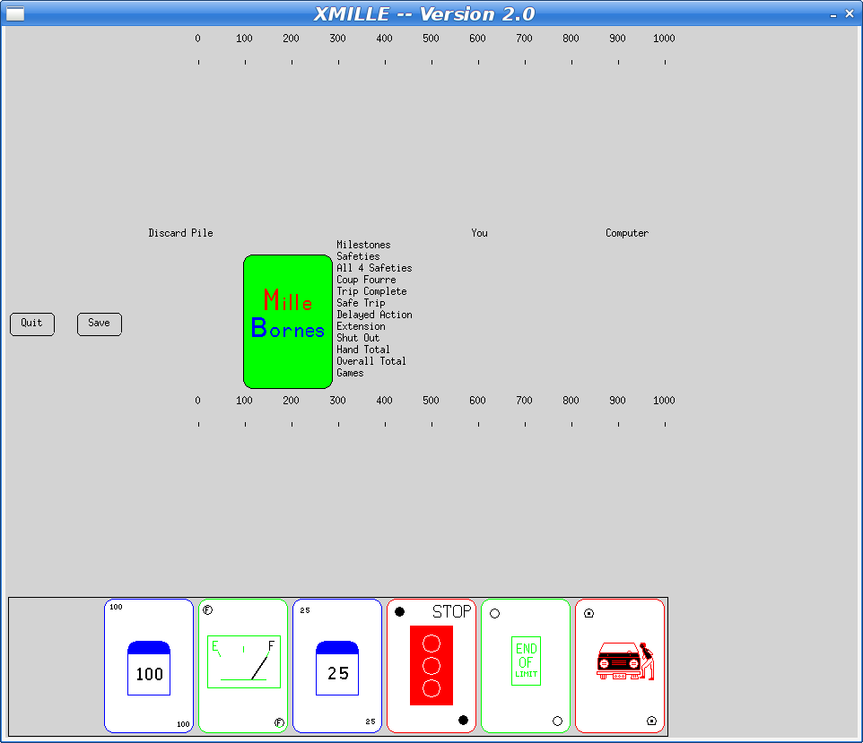
The reason the 'xmille' source is missing copyright and license information from the 'mille' files is that they were copied in before that information was added upstream. Xmille forked from Mille around 1987 or so. I wrote the UI parts for the system I had at the time, which was running X10R4. A very basic port to X11 was done at some point, and that's what Debian has in the archive today.
At some point in the 90s, I ported Xmille to the Athena widget set, including several custom widgets in an Xaw extension library, Xkw. It's a lot better than the version in Debian, including displaying the cards correctly (the Debian version has some pretty bad color issues).
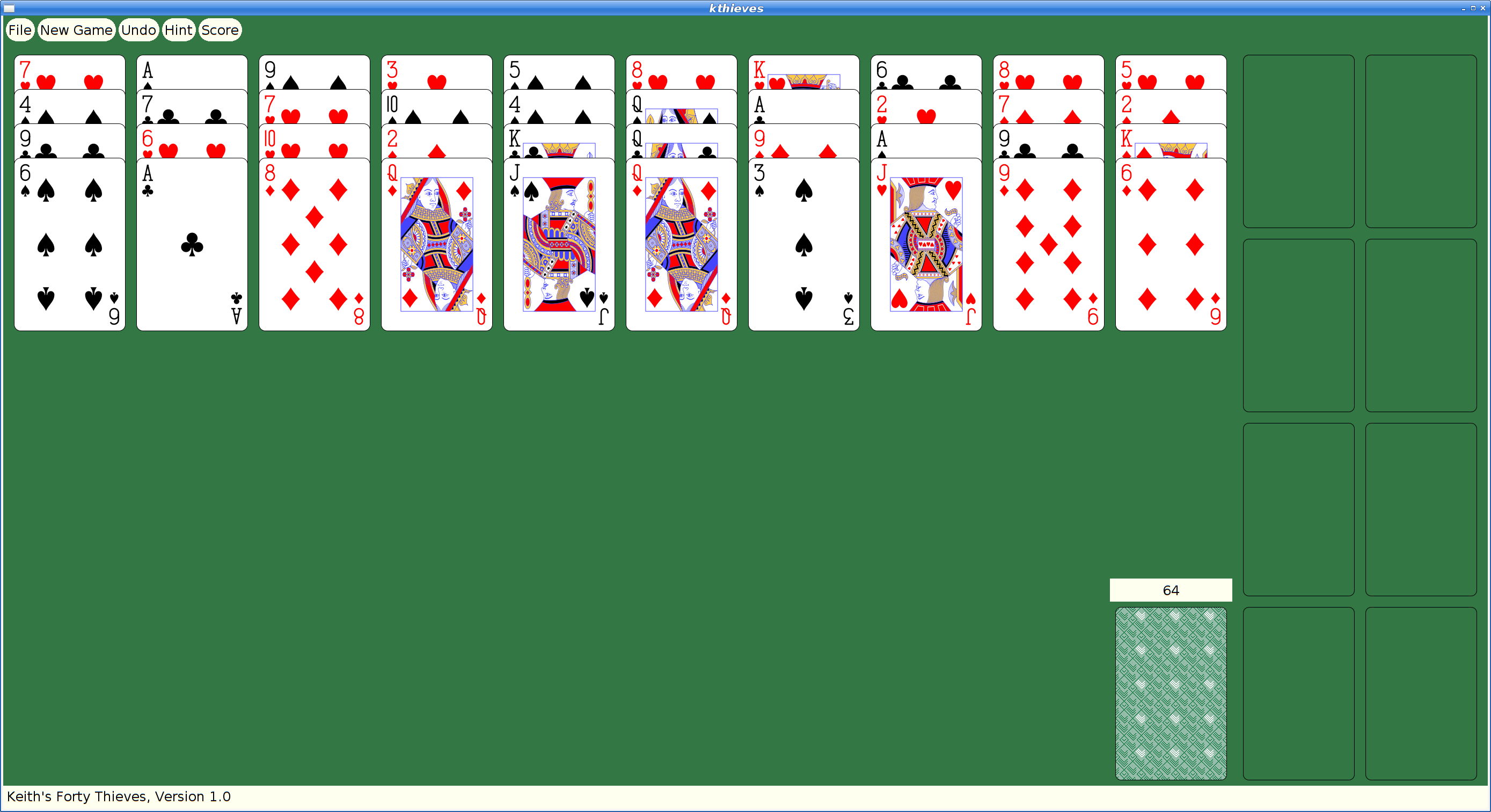
Here's what the current Debian version looks like:
Fixing The Bug
To fix the missing copyright and license information, I imported the mille source code into the "latest" Xaw-based version. The updated mille code had a number of bug fixes and improvements, along with the copyright information.
That should have been sufficient to resolve the issue and I could have constructed a suitable source package from whatever bits were needed and and uploaded that as a replacement 'xmille' package.
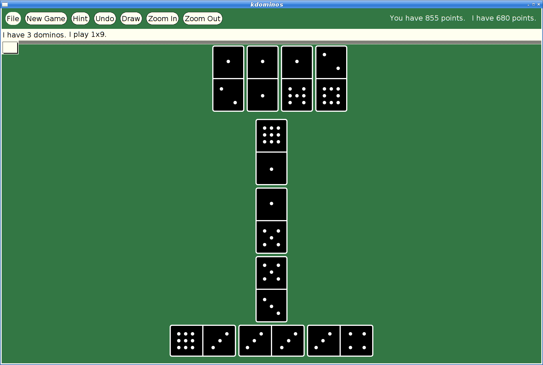
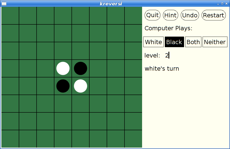
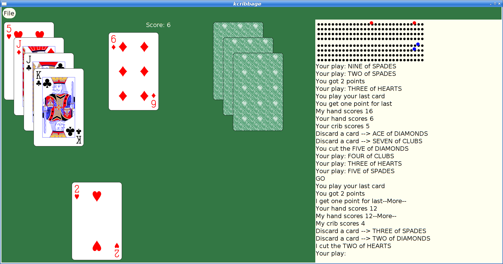
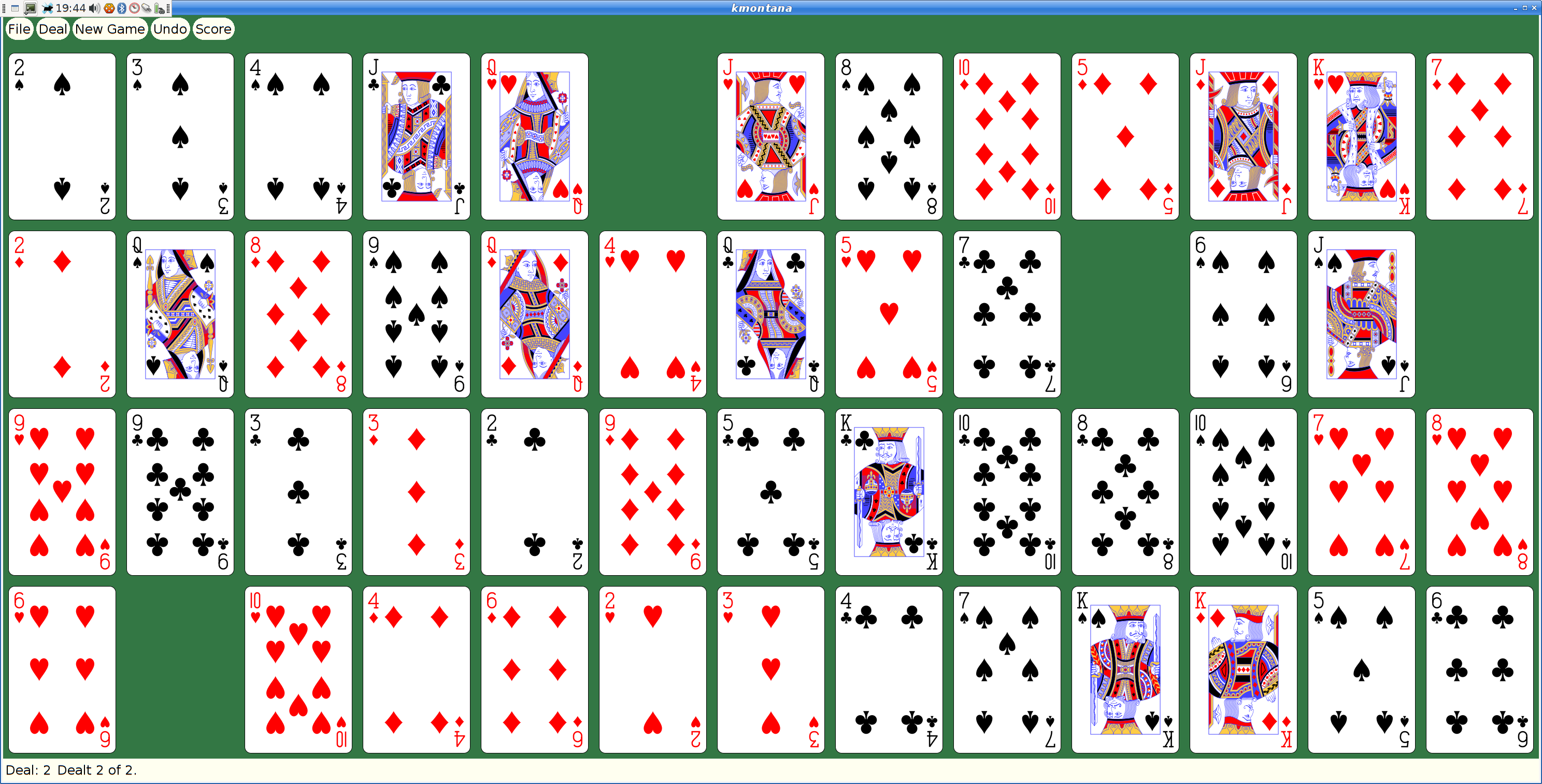
However, at some later point, I had actually merged xmille into a larger package, 'kgames', which also included a number of other games, including Reversi, Dominoes, Cribbage and ten Solitaire/Patience variants. (as an aside, those last ten games formed the basis for my Patience Palm Pilot application, which seems to have inspired an Android App of the same name...)
So began my yak shaving holiday.
Building Kgames in 2020
Ok, so getting this old source code running should be easy, right? It's just a bunch of C code designed in the 80s and 90s to work on VAXen and their kin. How hard could it be?
Everything was a 32-bit computer back then; pointers and ints were both 32 bits, so you could cast them with wild abandon and cause no problems. Today, testing revealed segfaults in some corners of the code.
It's K&R C code. Remember that the first version of ANSI-C didn't come out until 1989, and it was years later that we could reliably expect to find an ANSI compiler with a random Unix box.
It's X11 code. Fortunately (?), X11 hasn't changed since these applications were written, so at least that part still works just fine. Imagine trying to build Windows or Mac OS code from the early 90's on a modern OS...
I decided to dig in and add prototypes everywhere; that found a lot of pointer/int casting issues, as well as several lurking bugs where the code was just plain broken.
After a day or so, I had things building and running and was no longer hitting crashes.
Kgames 1.0 uploaded to Debian New Queue
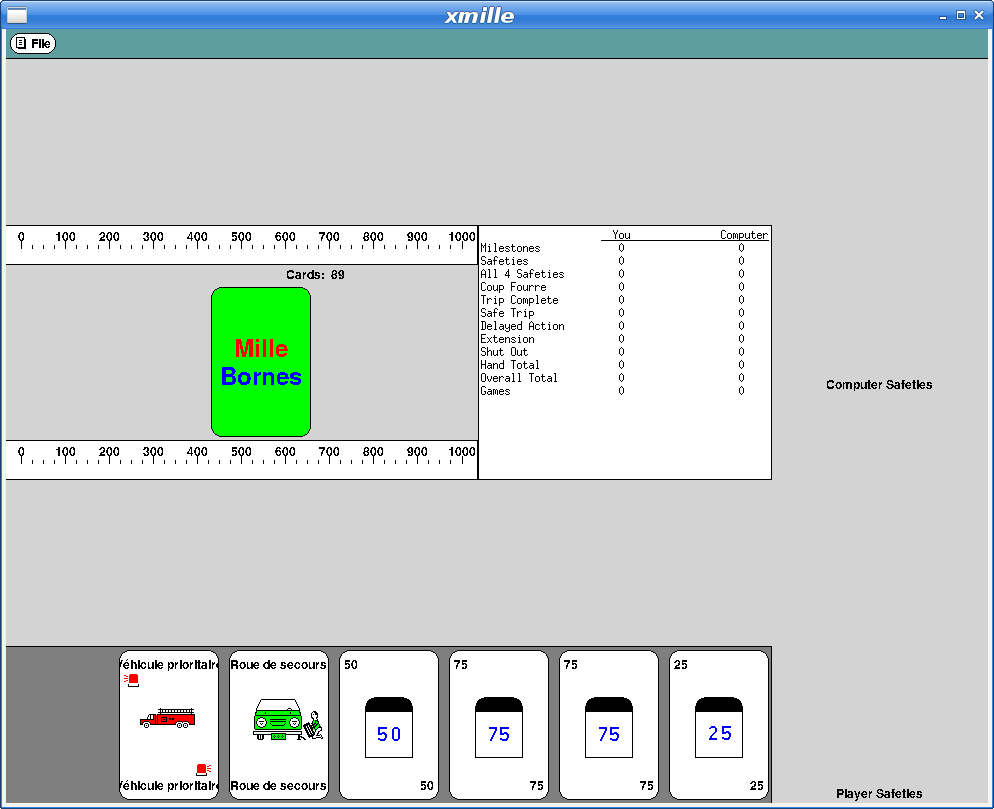
With that done, I decided I could at least upload the working bits to the Debian archive and close the bug reported above. kgames 1.0-2 may eventually get into unstable, presumably once the Debian FTP team realizes just how important fixing this bug is. Or something.
Here's what xmille looks like in this version:
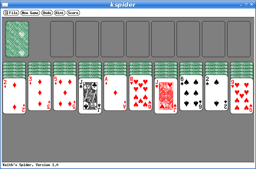
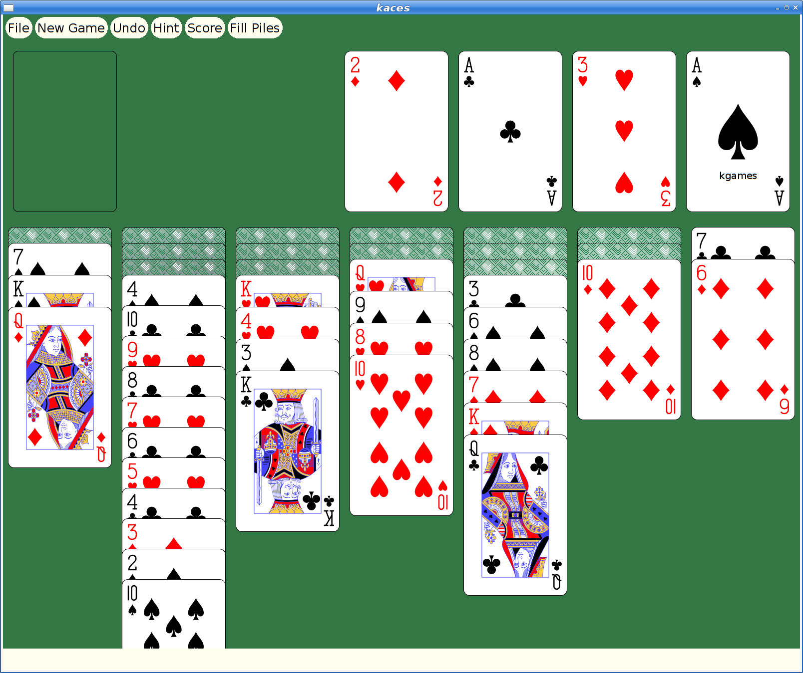
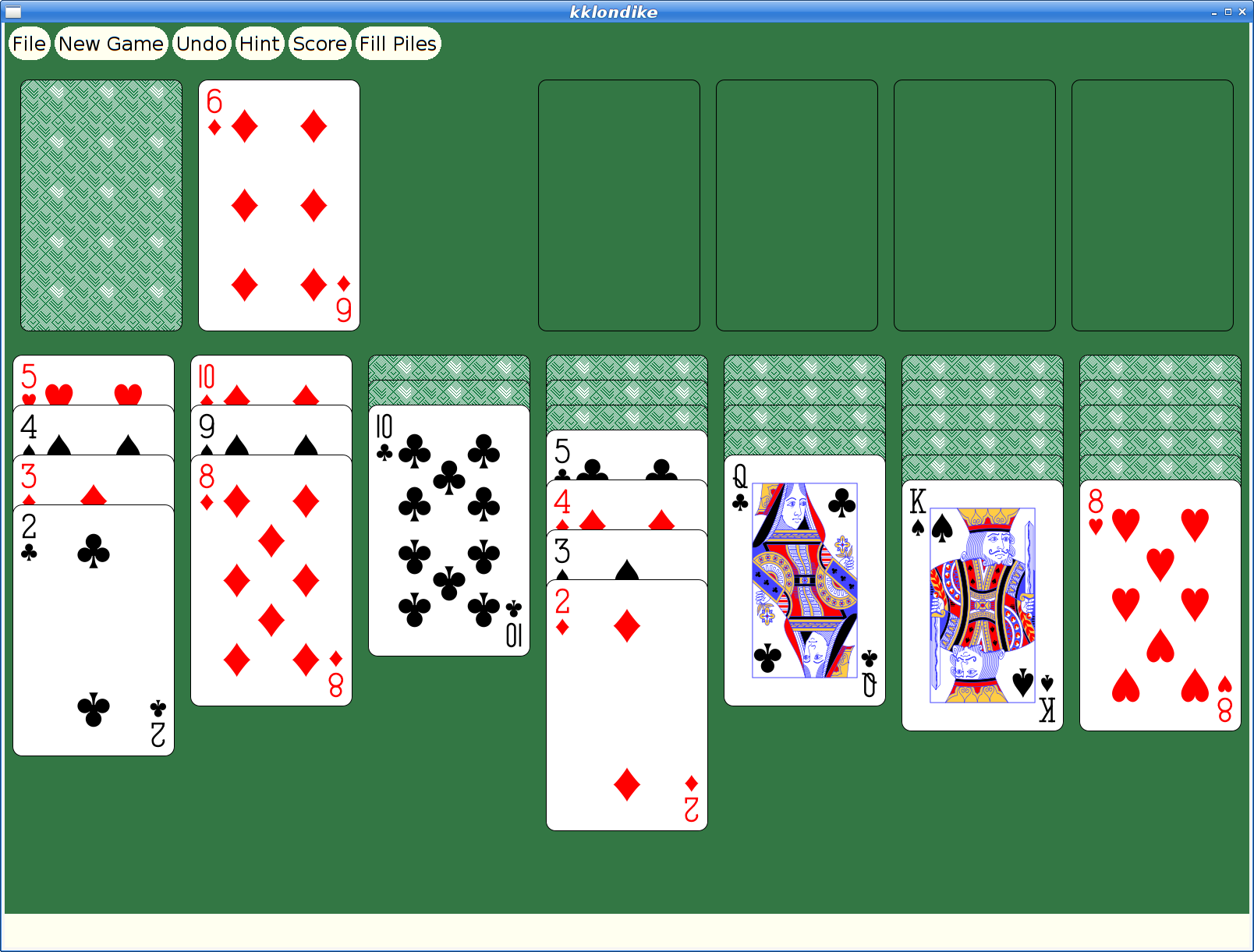
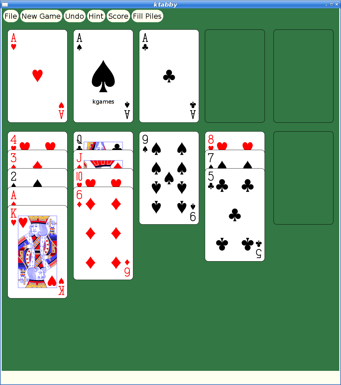
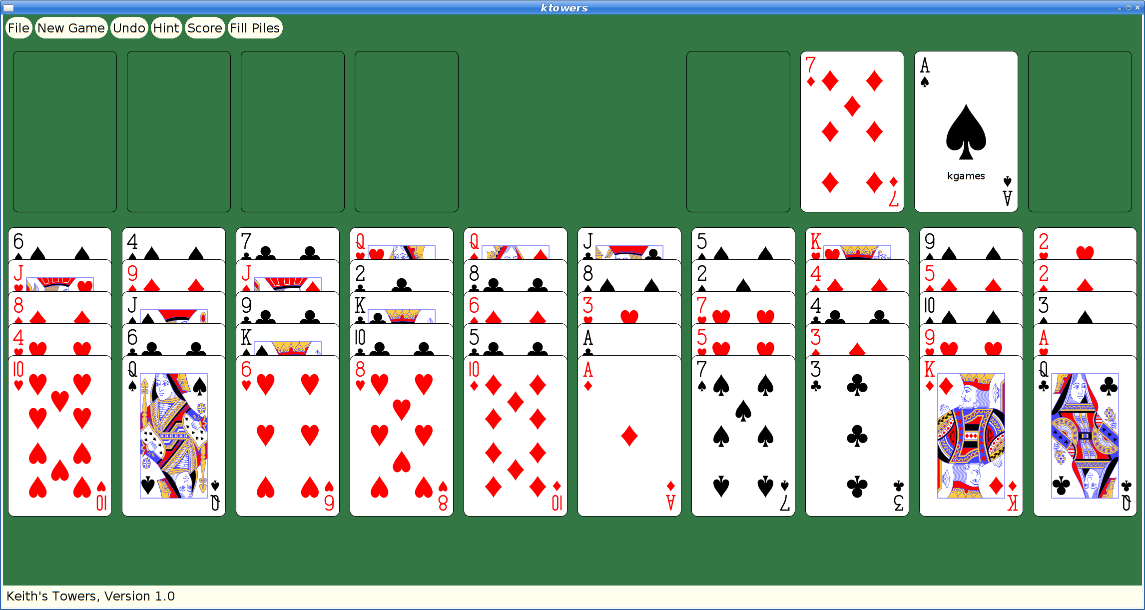
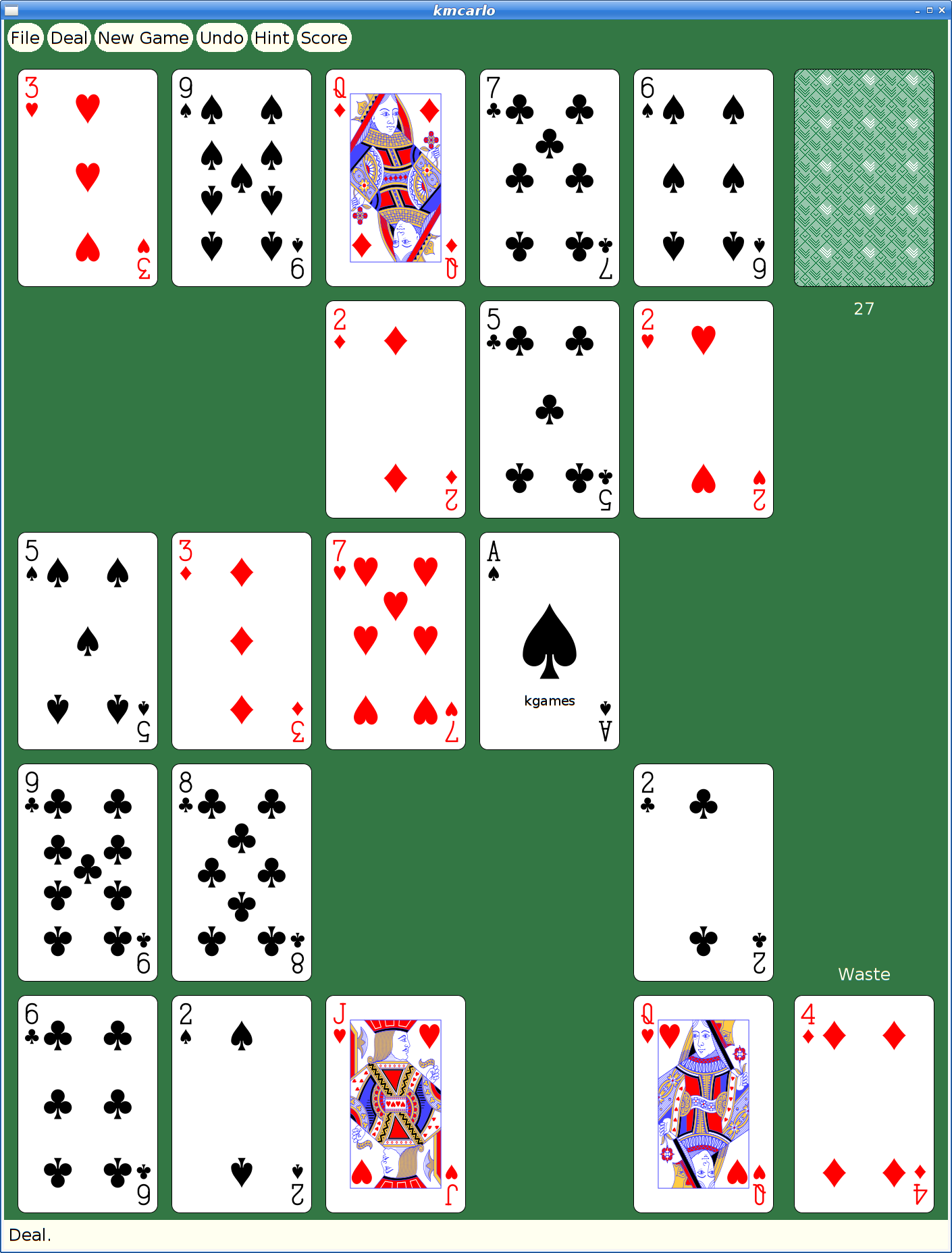
And here's my favorite solitaire variant too:
But They Look So Old
Yeah, Xaw applications have a rustic appearance which may appeal to some, but for people with higher resolution monitors and “well seasoned” eyesight, squinting at the tiny images and text makes it difficult to enjoy these games today.
How hard could it be to update them to use larger cards and scalable fonts?
Xkw version 2.0
I decided to dig in and start hacking the code, starting by adding new widgets to the Xkw library that used cairo for drawing instead of core X calls. Fortunately, the needs of the games were pretty limited, so I only needed to implement a handful of widgets:
KLabel. Shows a text string. It allows the string to be left, center or right justified. And that's about it.
KCommand. A push button, which uses KLabel for the underlying presentation.
KToggle. A push-on/push-off button, which uses KCommand for most of the implementation. Also supports 'radio groups' where pushing one on makes the others in the group turn off.
KMenuButton. A button for bringing up a menu widget; this is some pretty simple behavior built on top of KCommand.
KSimpleMenu, KSmeBSB, KSmeLine. These three create pop-up menus; KSimpleMenu creates a container which can hold any number of KSmeBSB (string) and KSmeLine (separator lines) objects).
KTextLine. A single line text entry widget.
The other Xkw widgets all got their rendering switched to using cairo, plus using double buffering to make updates look better.
SVG Playing Cards
Looking on wikimedia, I found a page referencing a large number of playing cards in SVG form That led me to Adrian Kennard's playing card web site that let me customize and download a deck of cards, licensed using the CC0 Public Domain license.
With these cards, I set about rewriting the Xkw playing card widget, stripping out three different versions of bitmap playing cards and replacing them with just these new SVG versions.
SVG Xmille Cards
Ok, so getting regular playing cards was good, but the original goal was to update Xmille, and that has cards hand drawn by me. I could just use those images, import them into cairo and let it scale them to suit on the screen. I decided to experiment with inkscape's bitmap tracing code to see what it could do with them.
First, I had to get them into a format that inkscape could parse. That turned out to be a bit tricky; the original format is as a set of X bitmap layers; each layer painting a single color. I ended up hacking the Xmille source code to generate the images using X, then fetching them with XGetImage and walking them to construct XPM format files which could then be fed into the portable bitmap tools to create PNG files that inkscape could handle.
The resulting images have a certain charm:

I did replace the text in the images to make it readable, otherwise these are untouched from what inkscape generated.
The Results
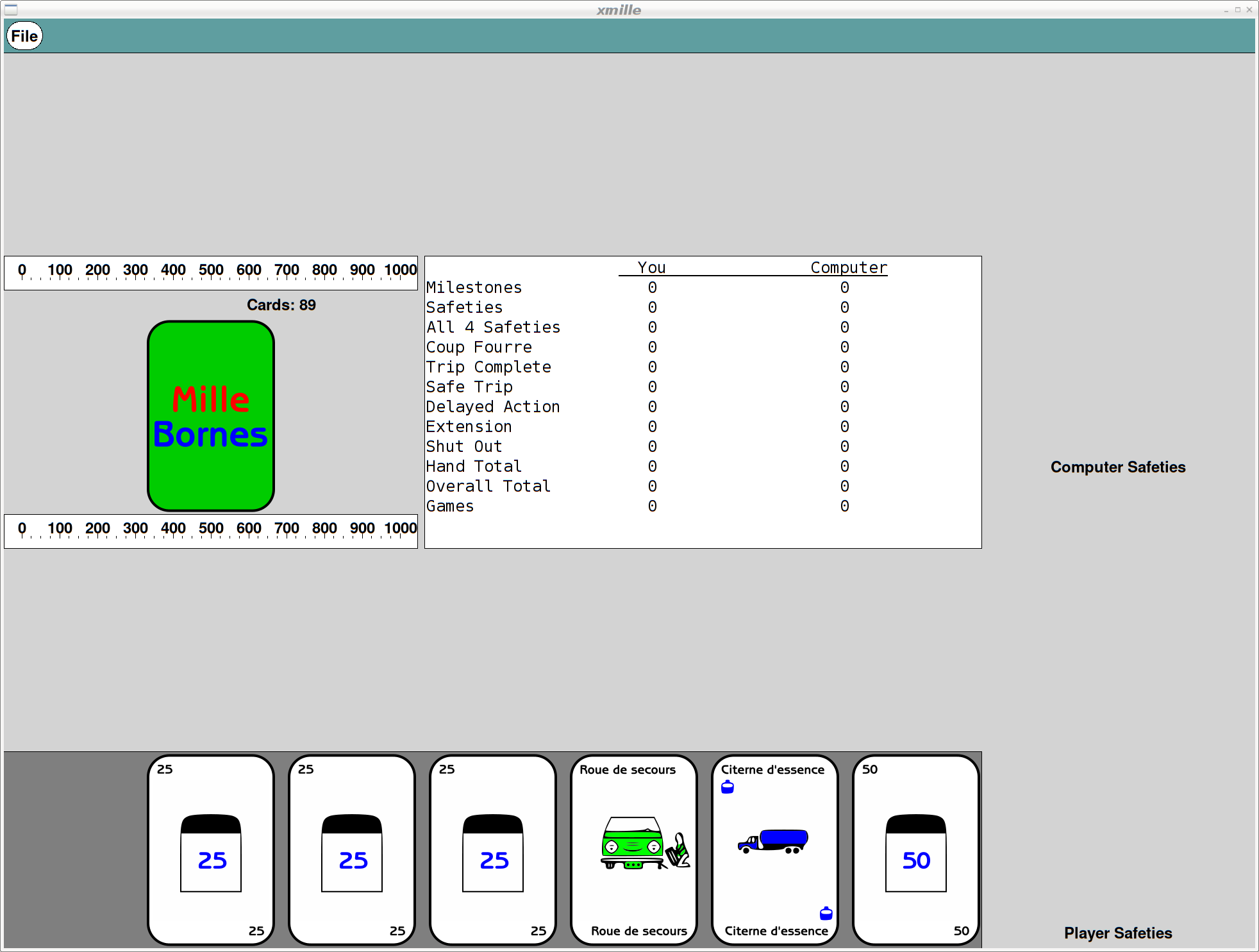
Remember that all of these are applications built using the venerable X toolkit; there are still some non-antialiased graphics visible as the shaped buttons use the X Shape extension. But, all rendering is now done with cairo, so it's all anti-aliased and all scalable.
Here's what Xmille looks like after the upgrades:
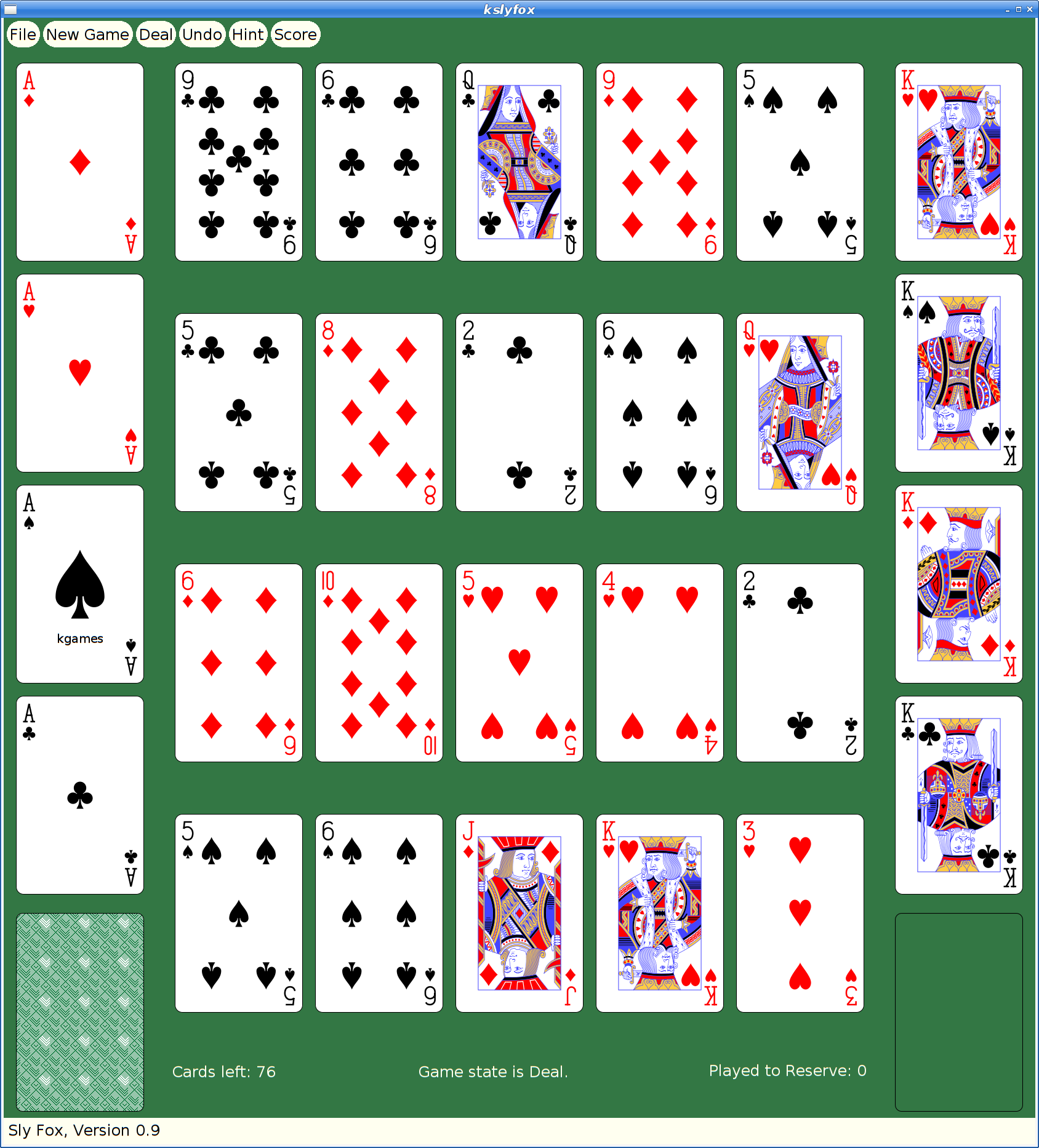
And here's spider:
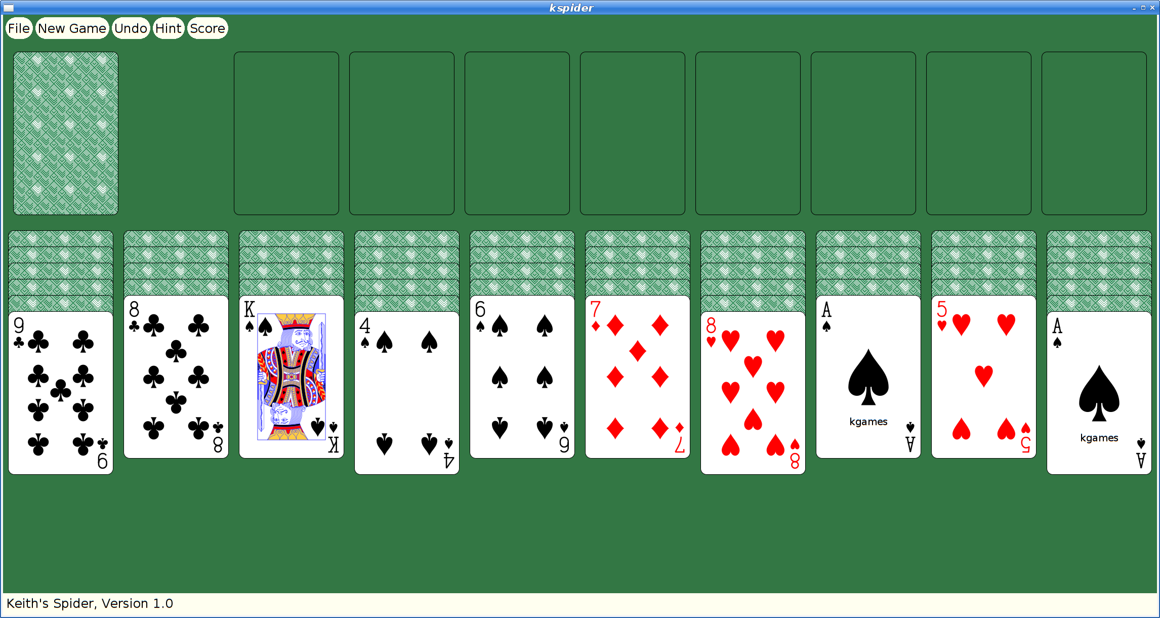
Once kgames 1.0 reaches Debian unstable, I'll upload these new versions.
Picolibc Updates
I thought work on picolibc would slow down at some point, but I keep finding more things that need work. I spent a few weeks working in libm and then discovered some important memory allocation bugs in the last week that needed attention too.
Cleaning up the Picolibc Math Library
Picolibc uses the same math library sources as newlib, which includes code from a range of sources:
SunPro (Sun Microsystems). This forms the bulk of the common code for the math library, with copyright dates stretching back to 1993. This code is designed for processors with FPUs and uses 'float' for float functions and 'double' for double functions.
NetBSD. This is where the complex functions came from, with Copyright dates of 2007.
FreeBSD. fenv support for aarch64, arm and sparc
IBM. SPU processor support along with a number of stubs for long-double support where long double is the same as double
Various processor vendors have provided processor-specific code for exceptions and a few custom functions.
Szabolcs Nagy and Wilco Dijkstra (ARM). These two re-implemented some of the more important functions in 2017-2018 for both float and double using double precision arithmetic and fused multiply-add primitives to improve performance for systems with hardware double precision support.
The original SunPro math code had been split into two levels at some point:
IEEE-754 functions. These offer pure IEEE-754 semantics, including return values and exceptions. They do not set the POSIX errno value. These are all prefixed with __ieee754_ and can be called directly by applications if desired.
POSIX functions. These can offer POSIX semantics, including setting errno and returning expected values when errno is set.
New Code Sponsored by ARM
Szabolcs Nagy and Wilco Dijkstra's work in the last few years has been to improve the performance of some of the core math functions, which is much appreciated. They've adopted a more modern coding style (C99) and written faster code at the expense of a larger memory foot print.
One interesting choice was to use double computations for the float implementations of various functions. This makes these functions shorter and more accurate than versions done using float throughout. However, for machines which don't have HW double, this pulls in soft double code which adds considerable size to the resulting binary and slows down the computations, especially if the platform does support HW float.
The new code also takes advantage of HW fused-multiply-add instructions. Those offer more precision than a sequence of primitive instructions, and so the new code can be much shorter as a result.
The method used to detect whether the target machine supported fma operations was slightly broken on 32-bit ARM platforms, where those with 'float' fma acceleration but without 'double' fma acceleration would use the shorter code sequence, but with an emulated fma operation that used the less-precise sequence of operations, leading to significant reductions in the quality of the resulting math functions.
I fixed the double fma detection and then also added float fma detection along with implementations of float and double fma for ARM and RISC-V. Now both of those platforms get fma-enhanced math functions where available.
Errno Adventures
I'd submitted patches to newlib a while ago that aliased the regular math library names to the __ieee754_ functions when the library was configured to not set errno, which is pretty common for embedded environments where a shared errno is a pain anyways.
Note the use of the word “can” in remark about the old POSIX wrapper functions. That's because all of these functions are run-time switchable between “_IEEE_” and “_POSIX_” mode using the _LIB_VERSION global symbol. When left in the usual _IEEE_ mode, none of this extra code was ever executed, so these wrapper functions never did anything beyond what the underlying __ieee754_ functions did.
The new code by Nagy and Dijkstra changed how functions are structured to eliminate the underlying IEEE-754 api. These new functions use tail calls to various __math_ error reporting functions. Those can be configured at library build time to set errno or not, centralizing those decisions in a few functions.
The result of this combination of source material is that in the default configuration, some library functions (those written by Nagy and Dijkstra) would set errno and others (the old SunPro code) would not. To disable all errno references, the library would need to be compiled with a set of options, -D_IEEE_LIBM to disable errno in the SunPro code and -DWANT_ERRNO=0 to disable errno in the new code. To enable errno everywhere, you'd set -D_POSIX_MODE to make the default value for _LIB_VERSION be _POSIX_ instead of _IEEE_.
To clean all of this up, I removed the run-time _LIB_VERSION variable and made that compile-time. In combination with the earlier work to alias the __ieee754_ functions to the regular POSIX names when _IEEE_LIBM was defined this means that the old SunPro POSIX functions now only get used when _IEEE_LIBM is not defined, and in that case the _LIB_VERSION tests always force use of the errno setting code. In addition, I made the value of WANT_ERRNO depend on whether _IEEE_LIBM was defined, so now a single definition (-D_IEEE_LIBM) causes all of the errno handling from libm to be removed, independent of which code is in use.
As part of this work, I added a range of errno tests for the math functions to find places where the wrong errno value was being used.
Exceptions
As an alternative to errno, C also provides for IEEE-754 exceptions through the fenv functions. These have some significant advantages, including having independent bits for each exception type and having them accumulate instead of sharing errno with a huge range of other C library functions. Plus, they're generally implemented in hardware, so you get exceptions for both library functions and primitive operations.
Well, you should get exceptions everywhere, except that the GCC soft float libraries don't support them at all. So, errno can still be useful if you need to know what happened in your library functions when using soft floats.
Newlib has recently seen a spate of fenv support being added for various architectures, so I decided that it would be a good idea to add some tests. I added tests for both primitive operations, and then tests for library functions to check both exceptions and errno values. Oddly, this uncovered a range of minor mistakes in various math functions. Lots of these were mistakes in the SunPro POSIX wrapper functions where they modified the return values from the __ieee754_ implementations. Simply removing those value modifications fixed many of those errors.
Fixing Memory Allocator bugs
Picolibc inherits malloc code from newlib which offers two separate implementations, one big and fast, the other small and slow(er). Selecting between them is done while building the library, and as Picolibc is expected to be used on smaller systems, the small and slow one is the default.
Contributed by someone from ARM back in 2012/2013, nano-mallocr reminds me of the old V7 memory allocator. A linked list, sorted in address order, holds discontiguous chunks of available memory.
Allocation is done by searching for a large enough chunk in the list. The first one large enough is selected, and if it is large enough, a chunk is split off and left on the free list while the remainder is handed to the application. When the list doesn't have any chunk large enough, sbrk is called to get more memory.
Free operations involve walking the list and inserting the chunk in the right location, merging the freed memory with any immediately adjacent chunks to reduce fragmentation.
The size of each chunk is stored just before the first byte of memory used by the application, where it remains while the memory is in use and while on the free list. The free list is formed by pointers stored in the active area of the chunk, so the only overhead for chunks in use is the size field.
Something Something Padding
To deal with the vagaries of alignment, the original nano-mallocr code would allow for there to be 'padding' between the size field and the active memory area. The amount of padding could vary, depending on the alignment required for a particular chunk (in the case of memalign, that padding can be quite large). If present, nano-mallocr would store the padding value in the location immediately before the active area and distinguish that from a regular size field by a negative sign.
The whole padding thing seems mysterious to me -- why would it ever be needed when the allocator could simply create chunks that were aligned to the required value and a multiple of that value in size. The only use I could think of was for memalign; adding this padding field would allow for less over-allocation to find a suitable chunk. I didn't feel like this one (infrequent) use case was worth the extra complexity; it certainly caused me difficulty in reading the code.
A Few Bugs
In reviewing the code, I found a couple of easy-to-fix bugs.
calloc was not checking for overflow in multiplication. This is something I've only heard about in the last five or six years -- multiplying the size of each element by the number of elements can end up wrapping around to a small value which may actually succeed and cause the program to mis-behave.
realloc copied new_size bytes from the original location to the new location. If the new size was larger than the old, this would read off the end of the original allocation, potentially disclosing information from an adjacent allocation or walk off the end of physical memory and cause some hard fault.
Time For Testing
Once I had uncovered a few bugs in this code, I decided that it would be good to write a few tests to exercise the API. With the tests running on four architectures in nearly 60 variants, it seemed like I'd be able to uncover at least a few more failures:
Error tests. Allocating too much memory and make sure the correct errors were returned and that nothing obviously untoward happened.
Touch tests. Just call the allocator and validate the return values.
Stress test. Allocate lots of blocks, resize them and free them. Make sure, using 'mallinfo', that the malloc arena looked reasonable.
These new tests did find bugs. But not where I expected them. Which is why I'm so fond of testing.
GCC Optimizations
One of my tests was to call calloc and make sure it returned a chunk of memory that appeared to work or failed with a reasonable value. To my surprise, on aarch64, that test never finished. It worked elsewhere, but on that architecture it hung in the middle of calloc itself. Which looked like this:
void * nano_calloc(malloc_size_t n, malloc_size_t elem)
{
    ptrdiff_t bytes;
    void * mem;

    if (__builtin_mul_overflow (n, elem, &bytes))
    {
    RERRNO = ENOMEM;
    return NULL;
    }
    mem = nano_malloc(bytes);
    if (mem != NULL) memset(mem, 0, bytes);
    return mem;
}
Note the naming here -- nano_mallocr uses nano_ prefixes in the code, but then uses #defines to change their names to those expected in the ABI. (No, I don't understand why either). However, GCC sees the real names and has some idea of what these functions are supposed to do. In particular, the pattern:
foo = malloc(n);
if (foo) memset(foo, '\0', n);
is converted into a shorter and semantically equivalent:
foo = calloc(n, 1);
Alas, GCC doesn't take into account that this optimization is occurring inside of the implementation of calloc.
Another sequence of code looked like this:
chunk->size = foo
nano_free((char *) chunk + CHUNK_OFFSET);
Well, GCC knows that the content of memory passed to free cannot affect the operation of the application, and so it converted this into:
nano_free((char *) chunk + CHUNK_OFFSET);
Remember that nano_mallocr stores the size of the chunk just before the active memory. In this case, nano_mallocr was splitting a large chunk into two pieces, setting the size of the left-over part and placing that on the free list. Failing to set that size value left whatever was there before for the size and usually resulted in the free list becoming quite corrupted.
Both of these problems can be corrected by compiling the code with a couple of GCC command-line switches (-fno-builtin-malloc and -fno-builtin-free).
Reworking Malloc
Having spent this much time reading through the nano_mallocr code, I decided to just go through it and make it easier for me to read today, hoping that other people (which includes 'future me') will also find it a bit easier to follow. I picked a couple of things to focus on:
All newly allocated memory should be cleared. This reduces information disclosure between whatever code freed the memory and whatever code is about to use the memory. Plus, it reduces the effect of un-initialized allocations as they now consistently get zeroed memory. Yes, this masks bugs. Yes, this goes slower. This change is dedicated to Kees Cook, but please blame me for it not him.
Get rid of the 'Padding' notion. Every time I read this code it made my brain hurt. I doubt I'll get any smarter in the future.
Realloc could use some love, improving its efficiency in common cases to reduce memory usage.
Reworking linked list walking. nano_mallocr uses a singly-linked free list and open-codes all list walking. Normally, I'd switch to a library implementation to avoid introducing my own bugs, but in this fairly simple case, I think it's a reasonable compromise to open-code the list operations using some patterns I learned while working at MIT from Bob Scheifler.
Discover necessary values, like padding and the limits of the memory space, from the environment rather than having them hard-coded.
Padding
To get rid of 'Padding' in malloc, I needed to make sure that every chunk was aligned and sized correctly. Remember that there is a header on every allocated chunk which is stored before the active memory which contains the size of the chunk. On 32-bit machines, that size is 4 bytes. If the machine requires allocations to be aligned on 8-byte boundaries (as might be the case for 'double' values), we're now going to force the alignment of the header to 8-bytes, wasting four bytes between the size field and the active memory.
Well, the existing nano_mallocr code also wastes those four bytes to store the 'padding' value. Using a consistent alignment for chunk starting addresses and chunk sizes has made the code a lot simpler and easier to reason about while not using extra memory for normal allocation. Except for memalign, which I'll cover in the next section.
realloc
The original nano_realloc function was as simple as possible:
mem = nano_malloc(new_size);
if (mem) {
    memcpy(mem, old, MIN(old_size, new_size));
    nano_free(old);
}
return mem;
However, this really performs badly when the application is growing a buffer while accumulating data. A couple of simple optimizations occurred to me:
If there's a free chunk just after the original location, it could be merged to the existing block and avoid copying the data.
If the original chunk is at the end of the heap, call sbrk() to increase the size of the chunk.
The second one seems like the more important case; in a small system, the buffer will probably land at the end of the heap at some point, at which point growing it to the size of available memory becomes quite efficient.
When shrinking the buffer, instead of allocating new space and copying, if there's enough space being freed for a new chunk, create one and add it to the free list.
List Walking
Walking singly-linked lists seem like one of the first things we see when learning pointer manipulation in C:
for (element = head; element; element = element->next)
    do stuff ...
However, this becomes pretty complicated when 'do stuff' includes removing something from the list:
prev = NULL;
for (element = head; element; element = element->next)
    ...
    if (found)
        break;
    ...
    prev = element

if (prev != NULL)
    prev->next = element->next;
else
    head = element->next;
An extra variable, and a test to figure out how to re-link the list. Bob showed me a simpler way, which I'm sure many people are familiar with:
for (ptr = &head; (element = *ptr); ptr = &(element->next))
    ...
    if (found)
        break;

*ptr = element->next;
Insertion is similar, as you would expect:
for (ptr = &head; (element = *ptr); ptr = &(element->next))
    if (found)
        break;

new_element->next = element;
*ptr = new_element;
In terms of memory operations, it's the same -- each 'next' pointer is fetched exactly once and the list is re-linked by performing a single store. In terms of reading the code, once you've seen this pattern, getting rid of the extra variable and the conditionals around the list update makes it shorter and less prone to errors.
In the nano_mallocr code, instead of using 'prev = NULL', it actually used 'prev = free_list', and the test for updating the head was 'prev == element', which really caught me unawares.
System Parameters
Any malloc implementation needs to know a couple of things about the system it's running on:
Address space. The maximum range of possible addresses sets the limit on how large a block of memory might be allocated, and hence the size of the 'size' field. Fortunately, we've got the 'size_t' type for this, so we can just use that.
Alignment requirements. These derive from the alignment requirements of the basic machine types, including pointers, integers and floating point numbers which are formed from a combination of machine requirements (some systems will fault if attempting to use memory with the wrong alignment) along with a compromise between memory usage and memory system performance.
I decided to let the system tell me the alignment necessary using a special type declaration and the 'offsetof' operation:
typedef struct {
    char c;
    union {
    void *p;
    double d;
    long long ll;
    size_t s;
    } u;
} align_t;

#define MALLOC_ALIGN        (offsetof(align_t, u))
Because C requires struct fields to be stored in order of declaration, the 'u' field would have to be after the 'c' field, and would have to be assigned an offset equal to the largest alignment necessary for any of its members. Testing on a range of machines yields the following alignment requirements:
| Architecture | Alignment |
|---|---|
| x86_64 | 8 |
| RISC-V | 8 |
| aarch64 | 8 |
| arm | 8 |
| x86 | 4 |
So, I guess I could have just used a constant value of '8' and not worried about it, but using the compiler-provided value means that running picolibc on older architectures might save a bit of memory at no real cost in the code.
Now, the header containing the 'size' field can be aligned to this value, and all allocated blocks can be allocated in units of this value.
memalign
memalign, valloc and pvalloc all allocate memory with restrictions on the alignment of the base address and length. You'd think these would be simple -- allocate a large chunk, align within that chunk and return the address. However, they also all require that the address can be successfully passed to free. Which means that the allocator needs to do some tricks to make it all work. Essentially, you allocate 'lots' of memory and then arrange that any bytes at the head and tail of the allocation can be returned to the free list.
The tail part is easy; if it's large enough to form a free chunk (which must contain the size and a 'next' pointer for the free list), it can be split off. Otherwise, it just sits at the end of the allocation being wasted space.
The head part is a bit tricky when it's not large enough to form a free chunk. That's where the 'padding' business came in handy; that can be as small as a 'size_t' value, which (on 32-bit systems) is only four bytes.
Now that we're giving up trying to reason about 'padding', any extra block at the start must be big enough to hold a free block, which includes the size and a next pointer. On 32-bit systems, that's just 8 bytes which (for most of our targets) is the same as the alignment value we're using. On 32-bit systems that can use 4-byte alignment, and on 64-bit systems, it's possible that the alignment required by the application for memalign and the alignment of a chunk returned by malloc might be off by too small an amount to create a free chunk.
So, we just allocate a lot of extra space; enough so that we can create a block of size 'toosmall + align' at the start and create a free chunk of memory out of that.
This works, and at least returns all of the unused memory back for other allocations.
Sending Patches Back to Newlib
I've sent the floating point fixes upstream to newlib where they've already landed on master. I've sent most of the malloc fixes, but I'm not sure they really care about seeing nano_mallocr refactored. If they do, I'll spend the time necessary to get the changes ported back to the newlib internal APIs and merged upstream.
Float/String Conversion in Picolibc: Enter “Ryū”
I recently wrote about this topic having concluded that the best route for now was to use the malloc-free, but imprecise, conversion routines in the tinystdio alternative.
A few days later, Sreepathi Pai pointed me at some very recent work in this area:
This is amazing! Thirty years after the papers referenced in the previous post, Ulf Adams came up with some really cool ideas and managed to reduce the math required for 64-bit conversion to 128 bit integers. This is a huge leap forward; we were doing long multi-precision computations before, and now it's all short enough to fit in registers (ok, a lot of registers, but still).
Getting the Ryū Code
The code is available on github: https://github.com/ulfjack/ryu. Reading through it, it's very clear that the author focuses on performance with lots of tuning for common cases. Still, it's quite readable, especially compared with the newlib multi-precision based code.
Picolibc String/Float conversion interface
Picolibc has some pretty basic needs for the float/string conversion code, it wants four functions:
__dtoa_engine
int
__dtoa_engine(double x, struct dtoa *dtoa, uint8_t max_digits, uint8_t max_decimals);
This converts the double
xto a string of decimal digits and a decimal exponent stored inside the 'dtoa' struct. It limits the total number of digits tomax_digitsand, optionally (when max_decimals is non-zero), limits the number of fractional digits tomax_decimals - 1. This latter supports 'f' formats. Returns the number of digits stored, which is <= max_digits. Less if the number can be accurately represented in fewer digits.__ftoa_engine
int
__ftoa_engine(float x, struct ftoa *ftoa, uint8_t max_digits, uint8_t max_decimals);
The same as
__dtoa_engine, except for floats.__atod_engine
double
__atod_engine(uint64_t m10, int e10);
To avoid needing to handle stdio inside the conversion function,
__atod_enginereceives fully parsed values, the base-10 significand (m10) and exponent (e10). The value to convert ism10 * pow(10, e10).__atof_engine
float
__atof_engine(uint32_t m10, int e10);
The same as
__atod_engine, except for floats.
With these, it can do printf, scanf, ecvt, fcvt, gcvt, strtod, strtof and atof.
Porting Ryū to Picolibc
The existing Ryū float-to-string code always generates the number of
digits necessary for accurate output. I had to hack it up to generate
correctly rounded shorter output when max_digits or max_decimals
were smaller. I'm not sure I managed to do that correctly, but at
least it appears to be passing all of the test cases I have. In normal
operation, Ryū iteratively removes digits from the answer that aren't
necessary to disambiguate with neighboring values.
What I changed was to keep removing digits using that method until the answer had few enough digits to fit in the desired length. There's some tricky rounding code that adjusts the final result and I had to bypass that if I'd removed extra digits.
That was about the only change necessary to the core algorithm. I also trimmed the code to only include the general case and not the performance improvements, then wrapped it with code to provide the _engine interface.
On the string-to-float side, most of what I needed to do was remove the string parsing bits at the start of the function and switch from performance-optimized to space-optimized versions of a couple of internal routines.
Correctness Results
Because these new functions are now 'exact', I was able to adjust the picolibc tests to compare all of the bits for string/float conversion instead of having to permit a bit of slop in the answers. With those changes, the picolibc test suite passes, which offers some assurance that things aren't completely broken.
Size Results
Snek uses the 32-bit float versions of the conversion routines, and for that, the size difference is:
   text    data     bss     dec     hex filename
  59068      44   37968   97080   17b38 snek-qemu-riscv-orig.elf
  59430      44   37968   97442   17ca2 snek-qemu-riscv-ryu.elf
    362
362 bytes added to gain accurate printf/strtof results seems like a good trade-off in this case.
Performance
I haven't measured performance at all, but I suspect that it won't be nearly as problematic on most platforms as the source code makes it appear. And that's because Ryū is entirely integer arithmetic with no floating point at all. This avoids using the soft fp code for platforms without hardware float support.
Pointers to the Code
I haven't merged this to picolibc master yet, it's on the ryu branch:
Review, especially of the hack above to return short results, would be greatly appreciated!
Thanks again to Ulf Adams for creating this code and to Sreepathi Pai for sending me a note about it!
Float/String Conversion in Picolibc
Exact conversion between strings and floats seems like a fairly straightforward problem. There are two related problems:
String to Float conversion. In this case, the goal is to construct the floating point number which most closely approximates the number represented by the string.
Float to String conversion. Here, the goal is to generate the shortest string which, when fed back into the String to Float conversion code, exactly reproduces the original value.
When linked together, getting from float to string and back to float is a “round trip”, and an exact pair of algorithms does this for every floating point value.
Solutions for both directions were published in the proceedings of the ACM SIGPLAN 1990 conference on Programming language design and implementation, with the string-to-float version written by William Clinger and the float-to-string version written by Guy Steele and Jon White. These solutions rely on very high precision integer arithmetic to get every case correct, with float-to-string requiring up to 1050 bits for the 64-bit IEEE floating point format.
That's a lot of bits.
Newlib Float/String Conversion
The original newlib code, written in 1998 by David M. Gay, has arbitrary-precision numeric code for these functions to get exact results. However, it has the disadvantages of performing numerous memory allocations, consuming considerable space for the code, and taking a long time for conversions.
The first disadvantage, using malloc during conversion, ended up causing a number of CVEs because the results of malloc were not being checked. That's bad on all platforms, but especially bad for embedded systems where reading and writing through NULL pointers may have unknown effects.
Upstream newlib applied a quick fix to check the allocations and call
abort. Again, on platforms with an OS, that at least provides a
way to shut down the program and let the operating environment figure
out what to do next. On tiny embedded systems, there may not be any
way to log an error message or even restart the system.
Ok, so we want to get rid of the calls to abort and have the error reported back through the API call which caused the problem. That's got two issues, one mere technical work, and another mere re-interpretation of specifications.
Let's review the specification issue. The libc APIs involved here are:
Input:
- scanf
- strtod
- atof
Output:
- printf
- ecvt, fcvt
- gcvt
Scanf and printf are both documented to set errno to ENOMEM when they run out of memory, but none of the other functions takes that possibility into account. So we'll make some stuff up and hope it works out:
strtod. About the best we can do is report that no conversion was performed.
atof. Atof explicitly fails to detect any errors, so all we can do is return zero. Maybe returning NaN would be better?
ecvt, fcvt and gcvt. These return a pointer, so they can return NULL on failure.
Now, looking back at the technical challenge. That's a “simple” matter of inserting checks at each allocation, or call which may result in an allocation, and reporting failure back up the call stack, unwinding any intermediate state to avoid leaking memory.
Testing Every Possible Allocation Failure
There are a lot of allocation calls in the newlib code. And the call stack can get pretty deep. A simple visual inspection of the code didn't seem sufficient to me to validate the allocation checking code.
So I instrumented malloc, making it count the number of allocations and fail at a specific one. Now I can count the total number of allocations done over the entire test suite run for each API involved and then run the test suite that many times, failing each allocation in turn and checking to make sure we recover correctly. By that, I mean:
- No stores through NULL pointers
- Report failure to the application
- No memory leaks
There were about 60000 allocations to track, so I ran the test suite that many times, which (with the added malloc tracing enabled) took about 12 hours.
Bits Pushed to the Repository
With the testing complete, I'm reasonably confident that the code is now working, and that these CVEs are more completely squashed. If someone is interested in back-porting the newlib fixes upstream to newlib, that would be awesome. It's not completely trivial as this part of picolibc has diverged a bit due to the elimination of the reent structure.
Picolibc's “Tinystdio” Float/String Conversion
Picolibc contains a complete replacement for stdio which was originally adopted from avr libc. That's a stdio implementation designed to run on 8-bit Atmel processors and focuses on very limited memory use and small code size. It does this while maintaining surprisingly complete support for C99 printf and scanf support.
However, it also does this without any arbitrary precision arithmetic, which means it doesn't get the right answer all of the time. For most embedded systems, this is usually a good trade off -- floating point input and output are likely to be largely used for diagnostics and debugging, so “mostly” correct answers are probably sufficient.
The original avr-libc code only supports 32-bit floats, as that's all the ABI on those processors has. I extended that to 64-, 80- and 128- bit floats to cover double and long double on x86 and RISC-V processors. Then I spent a bunch of time adjusting the code to get it to more accurately support C99 standards.
Tinystdio also had strtod support, but it was missing ecvt, fcvt and gcvt. For those, picolibc was just falling back to the old newlib code, which introduced all of the memory allocation issues we've just read about.
Fixing that so that tinystdio was self-contained and did ecvt, fcvt and gcvt internally required writing those functions in terms of the float-to-string primitives already provided in tinystdio to support printf. gcvt is most easily supported by just calling sprintf.
Once complete, the default picolibc build, using tinystdio, no longer does any memory allocation for float/string conversions.
Slightly Better Iterative Spline Decomposition
My colleague Bart Massey (who is a CS professor at Portland State University) reviewed my iterative spline algorithm article and had an insightful comment — we don't just want any spline decomposition which is flat enough, what we really want is a decomposition for which every line segment is barely within the specified flatness value.
My initial approach was to keep halving the length of the spline segment until it was flat enough. This definitely generates a decomposition which is flat enough everywhere, but some of the segments will be shorter than they need to be, by as much as a factor of two.
As we'll be taking the resulting spline and doing a lot more computation with each segment, it makes sense to spend a bit more time finding a decomposition with fewer segments.
The Initial Search
Here's how the first post searched for a 'flat enough' spline section:
t = 1.0f;

/* Iterate until s1 is flat */
do {
    t = t/2.0f;
    _de_casteljau(s, s1, s2, t);
} while (!_is_flat(s1));
Bisection Method
What we want to do is find an approximate solution for the function:
flatness(t) = tolerance
We'll use the Bisection method to find the value of t for which the flatness is no larger than our target tolerance, but is at least as large as tolerance - ε, for some reasonably small ε.
float       hi = 1.0f;
float       lo = 0.0f;

/* Search for an initial section of the spline which
 * is flat, but not too flat
 */
for (;;) {

    /* Average the lo and hi values for our
     * next estimate
     */
    float t = (hi + lo) / 2.0f;

    /* Split the spline at the target location
     */
    _de_casteljau(s, s1, s2, t);

    /* Compute the flatness and see if s1 is flat
     * enough
     */
    float flat = _flatness(s1);

    if (flat <= SCALE_FLAT(SNEK_DRAW_TOLERANCE)) {

        /* Stop looking when s1 is close
         * enough to the target tolerance
         */
        if (flat >= SCALE_FLAT(SNEK_DRAW_TOLERANCE - SNEK_FLAT_TOLERANCE))
            break;

        /* Flat: t is the new lower interval bound */
        lo = t;
    } else {

        /* Not flat: t is the new upper interval bound */
        hi =  t;
    }
}
This searches for a place to split the spline where the initial portion is flat but not too flat. I set SNEK_FLAT_TOLERANCE to 0.01, so we'll pick segments which have flatness between 0.49 and 0.50.
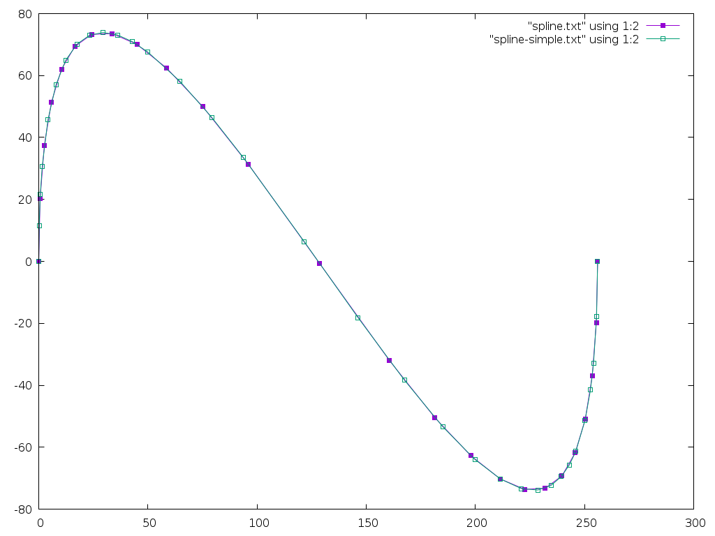
The benefit from the search is pretty easy to understand by looking at
the number of points generated compared with the number of
_de_casteljau and _flatness calls:
| Search | Calls | Points |
|---|---|---|
| Simple | 150 | 33 |
| Bisect | 229 | 25 |
And here's an image comparing the two:
A Closed Form Approach?
Bart also suggests attempting to find an analytical solution to decompose the spline. What we need is to is take the flatness function and find the spline which makes it equal to the desired flatness. If the spline control points are a, b, c, and d, then the flatness function is:
ux = (3×b.x - 2×a.x - d.x)²
uy = (3×b.y - 2×a.y - d.y)²
vx = (3×c.x - 2×d.x - a.x)²
vy = (3×c.y - 2×d.y - a.y)²

flat = max(ux, vx) + max(uy, vy)
When the spline is split into two pieces, all of the control points for the new splines are determined by the original control points and the 't' value which sets where the split happens. What we want is to find the 't' value which makes the flat value equal to the desired tolerance. Given that the binary search runs De Casteljau and the flatness function almost 10 times for each generated point, there's a lot of opportunity to go faster with a closed form solution.
Update: Fancier Method Found!
Bart points me at two papers:
- Flattening quadratic Béziers by Raph Levien
- Precise Flattening of Cubic Bézier Segments by Thomas F. Hain, Athar L. Ahmad, and David D. Langan
Levien's paper offers a great solution for quadratic Béziers by directly computing the minimum set of line segments necessary to approximate within a specified flatness. However, it doesn't generalize to cubic Béziers.
Hain, Ahmad and Langan do provide a directly computed decomposition of a cubic Bézier. This is done by constructing a parabolic approximation to the first portion of the spline and finding a 't' value which produces the desired flatness. There are a pile of special cases to deal with when there isn't a good enough parabolic approximation. But, overall computational cost is lower than a straightforward binary decomposition, plus there's no recursion required.
This second algorithm has the same characteristics as my Bisection method as the last segment may have any flatness from zero through the specified tolerance; Levien's solution is neater in that it generates line segments of similar flatness across the whole spline.
Current Implementation
/*
 * Copyright © 2020 Keith Packard <keithp@keithp.com>
 *
 * This program is free software; you can redistribute it and/or modify
 * it under the terms of the GNU General Public License as published by
 * the Free Software Foundation, either version 3 of the License, or
 * (at your option) any later version.
 *
 * This program is distributed in the hope that it will be useful, but
 * WITHOUT ANY WARRANTY; without even the implied warranty of
 * MERCHANTABILITY or FITNESS FOR A PARTICULAR PURPOSE.  See the GNU
 * General Public License for more details.
 *
 * You should have received a copy of the GNU General Public License along
 * with this program; if not, write to the Free Software Foundation, Inc.,
 * 51 Franklin St, Fifth Floor, Boston, MA 02110-1301, USA.
 */

#include <stdbool.h>
#include <stdio.h>
#include <string.h>
#include <stdint.h>
#include <math.h>

typedef float point_t[2];
typedef point_t spline_t[4];

uint64_t num_flats;
uint64_t num_points;

#define SNEK_DRAW_TOLERANCE 0.5f
#define SNEK_FLAT_TOLERANCE 0.01f

/*
 * This actually returns flatness² * 16,
 * so we need to compare against scaled values
 * using the SCALE_FLAT macro
 */
static float
_flatness(spline_t spline)
{
    /*
     * This computes the maximum deviation of the spline from a
     * straight line between the end points.
     *
     * From https://hcklbrrfnn.files.wordpress.com/2012/08/bez.pdf
     */
    float ux = 3.0f * spline[1][0] - 2.0f * spline[0][0] - spline[3][0];
    float uy = 3.0f * spline[1][1] - 2.0f * spline[0][1] - spline[3][1];
    float vx = 3.0f * spline[2][0] - 2.0f * spline[3][0] - spline[0][0];
    float vy = 3.0f * spline[2][1] - 2.0f * spline[3][1] - spline[0][1];

    ux *= ux;
    uy *= uy;
    vx *= vx;
    vy *= vy;
    if (ux < vx)
        ux = vx;
    if (uy < vy)
        uy = vy;
    ++num_flats;

    /*
     *If we wanted to return the true flatness, we'd use:
     *
     * return sqrtf((ux + uy)/16.0f)
     */
    return ux + uy;
}

/* Convert constants to values usable with _flatness() */
#define SCALE_FLAT(f)   ((f) * (f) * 16.0f)

/*
 * Linear interpolate from a to b using distance t (0 <= t <= 1)
 */
static void
_lerp (point_t a, point_t b, point_t r, float t)
{
    int i;
    for (i = 0; i < 2; i++)
        r[i] = a[i]*(1.0f - t) + b[i]*t;
}

/*
 * Split 's' into two splines at distance t (0 <= t <= 1)
 */
static void
_de_casteljau(spline_t s, spline_t s1, spline_t s2, float t)
{
    point_t first[3];
    point_t second[2];
    int i;

    for (i = 0; i < 3; i++)
        _lerp(s[i], s[i+1], first[i], t);

    for (i = 0; i < 2; i++)
        _lerp(first[i], first[i+1], second[i], t);

    _lerp(second[0], second[1], s1[3], t);

    for (i = 0; i < 2; i++) {
        s1[0][i] = s[0][i];
        s1[1][i] = first[0][i];
        s1[2][i] = second[0][i];

        s2[0][i] = s1[3][i];
        s2[1][i] = second[1][i];
        s2[2][i] = first[2][i];
        s2[3][i] = s[3][i];
    }
}

/*
 * Decompose 's' into straight lines which are
 * within SNEK_DRAW_TOLERANCE of the spline
 */
static void
_spline_decompose(void (*draw)(float x, float y), spline_t s)
{
    /* Start at the beginning of the spline. */
    (*draw)(s[0][0], s[0][1]);

    /* Split the spline until it is flat enough */
    while (_flatness(s) > SCALE_FLAT(SNEK_DRAW_TOLERANCE)) {
        spline_t    s1, s2;
        float       hi = 1.0f;
        float       lo = 0.0f;

        /* Search for an initial section of the spline which
         * is flat, but not too flat
         */
        for (;;) {

            /* Average the lo and hi values for our
             * next estimate
             */
            float t = (hi + lo) / 2.0f;

            /* Split the spline at the target location
             */
            _de_casteljau(s, s1, s2, t);

            /* Compute the flatness and see if s1 is flat
             * enough
             */
            float flat = _flatness(s1);

            if (flat <= SCALE_FLAT(SNEK_DRAW_TOLERANCE)) {

                /* Stop looking when s1 is close
                 * enough to the target tolerance
                 */
                if (flat >= SCALE_FLAT(SNEK_DRAW_TOLERANCE - SNEK_FLAT_TOLERANCE))
                    break;

                /* Flat: t is the new lower interval bound */
                lo = t;
            } else {

                /* Not flat: t is the new upper interval bound */
                hi =  t;
            }
        }

        /* Draw to the end of s1 */
        (*draw)(s1[3][0], s1[3][1]);

        /* Replace s with s2 */
        memcpy(&s[0], &s2[0], sizeof (spline_t));
    }

    /* S is now flat enough, so draw to the end */
    (*draw)(s[3][0], s[3][1]);
}

void draw(float x, float y)
{
    ++num_points;
    printf("%8g, %8g\n", x, y);
}

int main(int argc, char **argv)
{
    spline_t spline = {
        { 0.0f, 0.0f },
        { 0.0f, 256.0f },
        { 256.0f, -256.0f },
        { 256.0f, 0.0f }
    };
    _spline_decompose(draw, spline);
    fprintf(stderr, "flats %lu points %lu\n", num_flats, num_points);
    return 0;
}
Decomposing Splines Without Recursion
To make graphics usable in Snek, I need to avoid using a lot of memory, especially on the stack as there's no stack overflow checking on most embedded systems. Today, I worked on how to draw splines with a reasonable number of line segments without requiring any intermediate storage. Here's the results from this work:
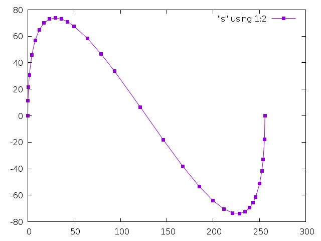
The Usual Method
The usual method I've used to convert a spline into a sequence of line segments is split the spline in half using DeCasteljau's algorithm recursively until the spline can be approximated by a straight line within a defined tolerance.
Here's an example from twin:
static void
_twin_spline_decompose (twin_path_t *path,
            twin_spline_t   *spline,
            twin_dfixed_t   tolerance_squared)
{
    if (_twin_spline_error_squared (spline) <= tolerance_squared)
    {
    _twin_path_sdraw (path, spline->a.x, spline->a.y);
    }
    else
    {
    twin_spline_t s1, s2;
    _de_casteljau (spline, &s1, &s2);
    _twin_spline_decompose (path, &s1, tolerance_squared);
    _twin_spline_decompose (path, &s2, tolerance_squared);
    }
}
The _de_casteljau function splits the spline at the midpoint:
static void
_lerp_half (twin_spoint_t *a, twin_spoint_t *b, twin_spoint_t *result)
{
    result->x = a->x + ((b->x - a->x) >> 1);
    result->y = a->y + ((b->y - a->y) >> 1);
}

static void
_de_casteljau (twin_spline_t *spline, twin_spline_t *s1, twin_spline_t *s2)
{
    twin_spoint_t ab, bc, cd;
    twin_spoint_t abbc, bccd;
    twin_spoint_t final;

    _lerp_half (&spline->a, &spline->b, &ab);
    _lerp_half (&spline->b, &spline->c, &bc);
    _lerp_half (&spline->c, &spline->d, &cd);
    _lerp_half (&ab, &bc, &abbc);
    _lerp_half (&bc, &cd, &bccd);
    _lerp_half (&abbc, &bccd, &final);

    s1->a = spline->a;
    s1->b = ab;
    s1->c = abbc;
    s1->d = final;

    s2->a = final;
    s2->b = bccd;
    s2->c = cd;
    s2->d = spline->d;
}
This is certainly straightforward, but suffers from an obvious flaw — there's unbounded recursion. With two splines in the stack frame, each containing eight coordinates, the stack will grow rapidly; 4 levels of recursion will consume more than 64 coordinates space. This can easily overflow the stack of a tiny machine.
De Casteljau Splits At Any Point
De Casteljau's algorithm is not limited to splitting splines at the midpoint. You can supply an arbitrary position t, 0 < t < 1, and you will end up with two splines which, drawn together, exactly match the original spline. I use 1/2 in the above version because it provides a reasonable guess as to how an arbitrary spline might be decomposed efficiently. You can use any value and the decomposition will still work, it will just change the recursion depth along various portions of the spline.
Iterative Left-most Spline Decomposition
What our binary decomposition does is to pick points t0 - tn such that splines t0..t1 through tn-1 .. tn are all 'flat'. It does this by recursively bisecting the spline, storing two intermediate splines on the stack at each level. If we look at just how the first, or 'left-most' spline is generated, that can be represented as an iterative process. At each step in the iteration, we split the spline in half:
S' = _de_casteljau(s, 1/2)
We can re-write this using the broader capabilities of the De Casteljau algorithm by splitting the original spline at decreasing points along it:
S[n] = _de_casteljau(s0, (1/2)ⁿ)
Now recall that the De Casteljau algorithm generates two splines, not just one. One describes the spline from 0..(1/2)ⁿ, the second the spline from (1/2)ⁿ..1. This gives us an iterative approach to generating a sequence of 'flat' splines for the whole original spline:
while S is not flat:
    n = 1
    do
        Sleft, Sright = _decasteljau(S, (1/2)ⁿ)
        n = n + 1
    until Sleft is flat
    result ← Sleft
    S = Sright
result ← S
We've added an inner loop that wasn't needed in the original algorithm, and we're introducing some cumulative errors as we step around the spline, but we don't use any additional memory at all.
Final Code
Here's the full implementation:
/*
 * Copyright © 2020 Keith Packard <keithp@keithp.com>
 *
 * This program is free software; you can redistribute it and/or modify
 * it under the terms of the GNU General Public License as published by
 * the Free Software Foundation, either version 3 of the License, or
 * (at your option) any later version.
 *
 * This program is distributed in the hope that it will be useful, but
 * WITHOUT ANY WARRANTY; without even the implied warranty of
 * MERCHANTABILITY or FITNESS FOR A PARTICULAR PURPOSE.  See the GNU
 * General Public License for more details.
 *
 * You should have received a copy of the GNU General Public License along
 * with this program; if not, write to the Free Software Foundation, Inc.,
 * 51 Franklin St, Fifth Floor, Boston, MA 02110-1301, USA.
 */

#include <stdbool.h>
#include <stdio.h>
#include <string.h>

typedef float point_t[2];
typedef point_t spline_t[4];

#define SNEK_DRAW_TOLERANCE 0.5f

/* Is this spline flat within the defined tolerance */
static bool
_is_flat(spline_t spline)
{
    /*
     * This computes the maximum deviation of the spline from a
     * straight line between the end points.
     *
     * From https://hcklbrrfnn.files.wordpress.com/2012/08/bez.pdf
     */
    float ux = 3.0f * spline[1][0] - 2.0f * spline[0][0] - spline[3][0];
    float uy = 3.0f * spline[1][1] - 2.0f * spline[0][1] - spline[3][1];
    float vx = 3.0f * spline[2][0] - 2.0f * spline[3][0] - spline[0][0];
    float vy = 3.0f * spline[2][1] - 2.0f * spline[3][1] - spline[0][1];

    ux *= ux;
    uy *= uy;
    vx *= vx;
    vy *= vy;
    if (ux < vx)
        ux = vx;
    if (uy < vy)
        uy = vy;
    return (ux + uy <= 16.0f * SNEK_DRAW_TOLERANCE * SNEK_DRAW_TOLERANCE);
}

static void
_lerp (point_t a, point_t b, point_t r, float t)
{
    int i;
    for (i = 0; i < 2; i++)
        r[i] = a[i]*(1.0f - t) + b[i]*t;
}

static void
_de_casteljau(spline_t s, spline_t s1, spline_t s2, float t)
{
    point_t first[3];
    point_t second[2];
    int i;

    for (i = 0; i < 3; i++)
        _lerp(s[i], s[i+1], first[i], t);

    for (i = 0; i < 2; i++)
        _lerp(first[i], first[i+1], second[i], t);

    _lerp(second[0], second[1], s1[3], t);

    for (i = 0; i < 2; i++) {
        s1[0][i] = s[0][i];
        s1[1][i] = first[0][i];
        s1[2][i] = second[0][i];

        s2[0][i] = s1[3][i];
        s2[1][i] = second[1][i];
        s2[2][i] = first[2][i];
        s2[3][i] = s[3][i];
    }
}

static void
_spline_decompose(void (*draw)(float x, float y), spline_t s)
{
    float       t;
    spline_t    s1, s2;

    (*draw)(s[0][0], s[0][1]);

    /* If s is flat, we're done */
    while (!_is_flat(s)) {
        t = 1.0f;

        /* Iterate until s1 is flat */
        do {
            t = t/2.0f;
            _de_casteljau(s, s1, s2, t);
        } while (!_is_flat(s1));

        /* Draw to the end of s1 */
        (*draw)(s1[3][0], s1[3][1]);

        /* Replace s with s2 */
        memcpy(&s[0], &s2[0], sizeof (spline_t));
    }
    (*draw)(s[3][0], s[3][1]);
}

void draw(float x, float y)
{
    printf("%8g, %8g\n", x, y);
}

int main(int argc, char **argv)
{
    spline_t spline = {
        { 0.0f, 0.0f },
        { 0.0f, 256.0f },
        { 256.0f, -256.0f },
        { 256.0f, 0.0f }
    };
    _spline_decompose(draw, spline);
    return 0;
}
Prototyping a Vulkan Extension — VK_MESA_present_period
I've been messing with application presentation through the Vulkan API for quite a while now, first starting by exploring how to make head-mounted displays work by creating DRM leases as described in a few blog posts: 1, 2, 3, 4.
Last year, I presented some work towards improving frame timing accuracy at the X developers conference. Part of that was about the Google Display Timing extension.
VK_GOOGLE_display_timing
VK_GOOGLE_display_timing is really two extensions in one:
Report historical information about when frames were shown to the user.
Allow applications to express when future frames should be shown to the user.
The combination of these two is designed to allow applications to get frames presented to the user at the right time. The biggest barrier to having things work perfectly all of the time is that the GPU has finite rendering performance, and can easily get behind if the application asks it to do more than it can in the time available.
When this happens, the previous frame gets stuck on the screen for extra time, and then the late frame gets displayed. In fact, because the software queues up a pile of stuff, several frames will often get delayed.
Once the application figures out that something bad happened, it can adjust future rendering, but the queued frames are going to get displayed at some point.
The problem is that the application has little control over the cadence of frames once things start going wrong.
Imagine the application is trying to render at 1/2 the native frame rate. Using GOOGLE_display_timing, it sets the display time for each frame by spacing them apart by twice the refresh interval. When a frame misses its target, it will be delayed by one frame. If the subsequent frame is ready in time, it will be displayed just one frame later, instead of two. That means you see two glitches, one for the delayed frame and a second for the "early" frame (not actually early, just early with respect to the delayed frame).
Specifying Presentation Periods
Maybe, instead of specifying when frames should be displayed, we should specify how long frames should be displayed. That way, when a frame is late, subsequent queued frames will still be displayed at the correct relative time. The application can use the first part of GOOGLE_display_timing to figure out what happened and correct at some later point, being careful to avoid generating another obvious glitch.
I really don't know if this is a better plan, but it seems worth experimenting with, so I decided to write some code and see how hard it was to implement.
Going In The Wrong Direction
At first, I assumed I'd have to hack up the X server, and maybe the kernel itself to make this work. So I started specifying changes to the X present extension and writing a pile of code in the X server.
Queuing the first presentation to the kernel was easy; with no previous presentation needing to be kept on the screen for a specified period, it just gets sent right along.
For subsequent presentations, I realized that I needed to wait until I learned when the earlier presentations actually happened, which meant waiting for a kernel event. That kernel event immediately generates an X event back to the Vulkan client, telling it when the presentation occurred.
Once I saw that both X and Vulkan were getting the necessary information at about the same time, I realized that I could wait in the Vulkan code rather than in the X server.
Window-system Independent Implementation
As part of the GOOGLE_display_timing implementation, each window system tells the common code when presentations have happened to record that information for the application. This provides the hook I need to send off pending presentations using that timing information to compute when they should be presented.
Almost. The direct-to-display (DRM) back-end worked great, but the X11 back-end wasn't very prompt about delivering this timing information, preferring to process X events (containing the timing information) only when the application was blocked in vkAcquireNextImageKHR. I hacked in a separate event handling thread so that events would be processed promptly and got things working.
VK_MESA_present_period
An application uses VK_MESA_present_period by including a VkPresentPeriodMESA structure in the pNext chain in the VkPresentInfoKHR structure passed to the vkQueuePresentKHR call.
typedef struct VkPresentPeriodMESA {
    VkStructureType    sType;
    const void*        pNext;
    uint32_t           swapchainCount;
    const int64_t*     pPresentPeriods;
} VkPresentPeriodMESA;
The fields in this structure are:
- sType. Set to VK_STRUCTURE_TYPE_PRESENT_PERIOD_MESA
- pNext. Points to the next extension structure in the chain (if any).
- swapchainCount. A copy of the swapchainCount field in the VkPresentInfoKHR structure.
- pPresentPeriods. An array, length swapchainCount, of presentation periods for each image in the call.
Positive presentation periods represent nanoseconds. Negative presentation periods represent frames. A zero value means the extension does not affect the associated presentation. Nanosecond values are rounded to the nearest upcoming frame so that a value of n * refresh_interval is the same as using a value of n frames.
The presentation period causes future images to be delayed at least until the specified interval after this image has been presented. Specifying both a presentation period in a previous frame and using GOOGLE_display_timing is well defined -- the presentation will be delayed until the later of the two times.
Status and Plans
The prototype (it's a bit haphazard, I'm afraid) code is available in my gitlab mesa repository. It depends on my GOOGLE_display_timing implementation, which has not been merged yet, so you may want to check that out to understand what this patch does.
As far as the API goes, I could easily be convinced to use some better way of switching between frames and nanoseconds, otherwise I think it's in pretty good shape.
I'm looking for feedback on whether this seems like a useful way to improve frame timing in Vulkan. Comments on how the code might be better structured would also be welcome; I'm afraid I open-coded a singly linked list in my haste...